FreeCAD: Creating 2D drawings from a 3D shape
Overview
In this article, we will explain how to create 2D drawings from the created 3D shape.
Operations
After cretating your 3D shape, switch workbench to TechDraw workbench
 .
.Select inserting new page
 to create page for 2D drawing.
Select original 3D shape in model tree and execute inserting view
 to insert a 2D drawing to the page.
-
Select the inserted view in model tree and set position, view direction, zoom ratio etc... at Data tab on Combo View. Then redraw the display
 to enable the changes.
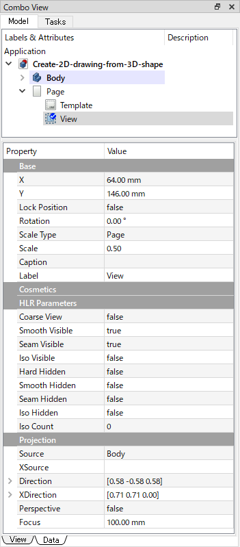
Data tab 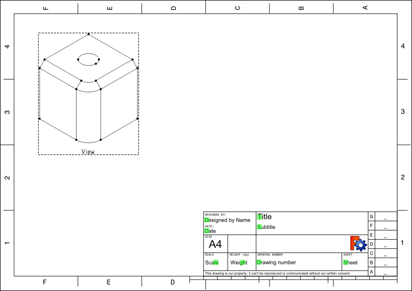
2D drawing Main properties of a view are as follows.
- X: X coordinate of display position
- Y: Y coordinate of display position
- Rotation: Rotation angles (The rotation axis is vertical to the screen)
- Scale: Zoom ratio
- Caption: Description text that is displayed on bottom of view
- Hard Hidden: Whether hidden lines are displayed or not
- Smooth Visible: Whether boundary lines of curved surfaces are displayed or not
- Direction: View dirction
- Perspective: If True, perspective projection is used. Other, orthogonal projection is used
- Focus: Degree of perspective projection in perspective mode.
Drawing direction will be adjust by view direction and rotation angle using "Direction" and "Rotation" parameters. Display position can be changed with draging frames of the view.
-
With same procedure, insert views that you want.
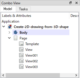
Model tree 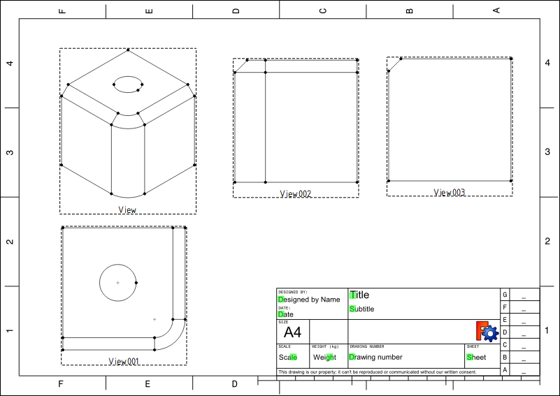
2D drawings -
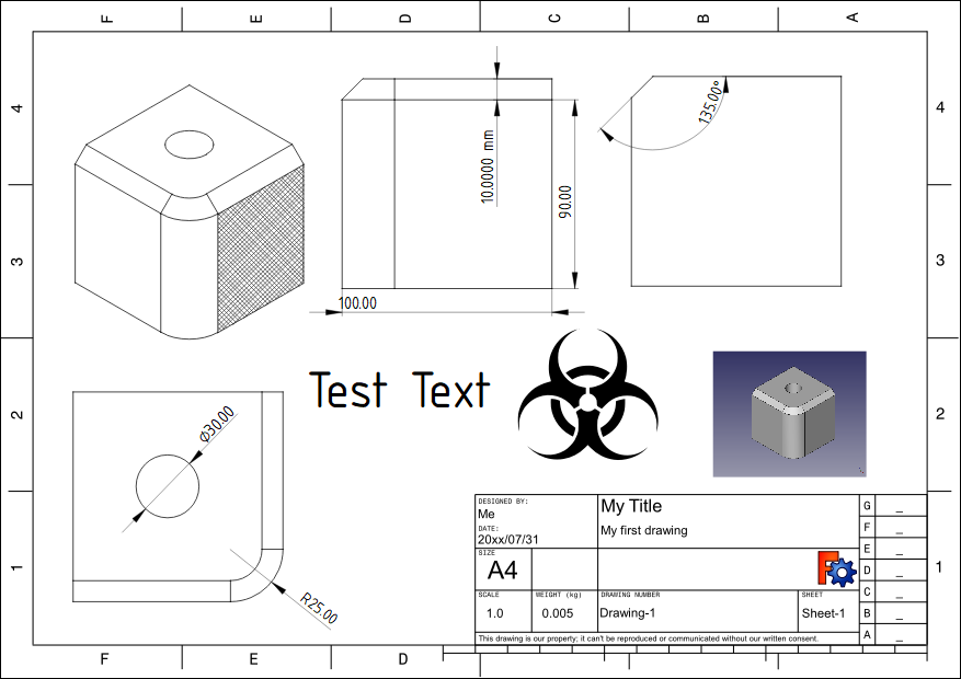
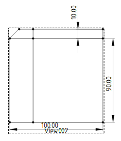
Then insert Dimensions into 2D drawings.
Select an edge (or select 2points with pressing Ctrl key) on the drawing and inserts dimention
 to selected edge. In the same way, you can insert vertical dimension
 and horizonal dimension
 .
.
Inserts vertical dimension and horizonal dimension Also it is possible to insert a diameter or radius by selecting circle or arc on the drawing and execute diameter
 or radius
 .
.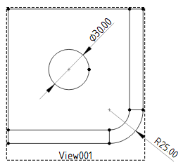
Inserts diameter and radius If you want inserts angle, select 2 edges and insert angle
 .
.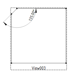
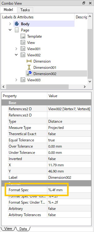
Inserts angle If you wnat to add unit to a dimension, select the dimension and edit "Format Spec" property at Data tab on Combo View.
Adds "mm" to dimension To delete dimension, select the dimension on the drawing and push Delete key.
-
It is possible to set hatching to the face. Select a face on the drawing and execute hatching
 .
.Also you can insert text
 , SVG format vector image
 or PNG/JPEG format bitmap image
 etc... to the drawing.
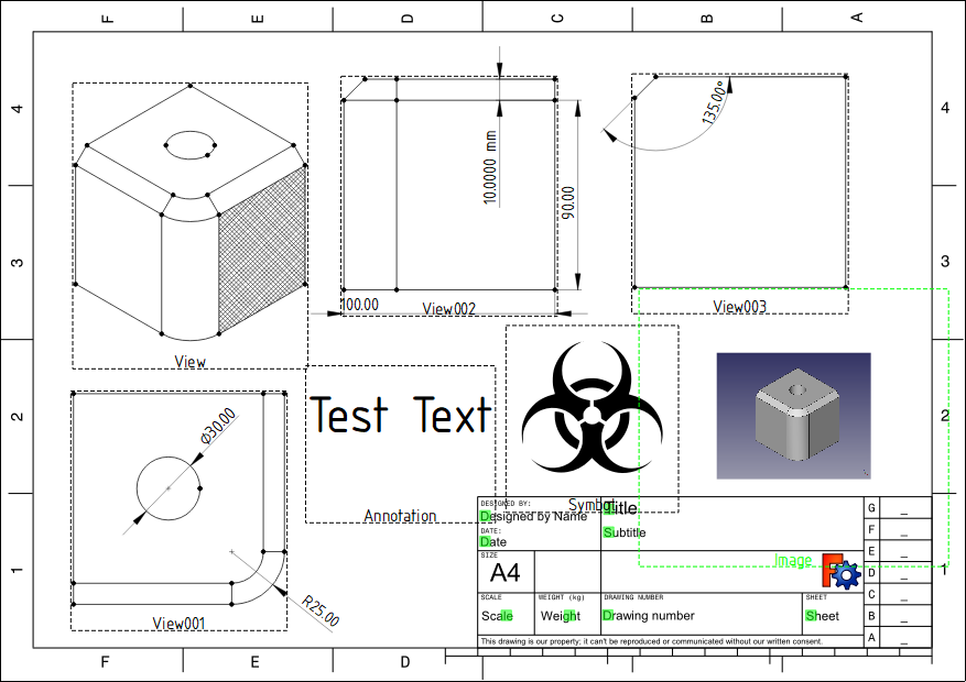
Inserts hatching, text, vector image, bitmap image. -
Then edit drawing's title etc... Click leading green rectangles at text on right-bottom of the drawing to show editing dialog. Edit text and click to change it.
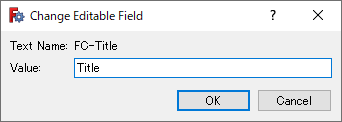
Change editable field dialog -
Finally, hide editing frame
 to check the drawing and save the page
 to a SVG format file.
If you need more editing, edit the SVG file with other general drawing tool (like Inkscape).
Example of drawing