FreeCAD: How to create a solid from a sketch by rotation extruding?
Create new document
 and switch workbench to Part Design workbench
 .
.-
Select New Sketch
 in toolbar and select XY plane as sketch plane on the dialog. Click to create a new sketch plane.
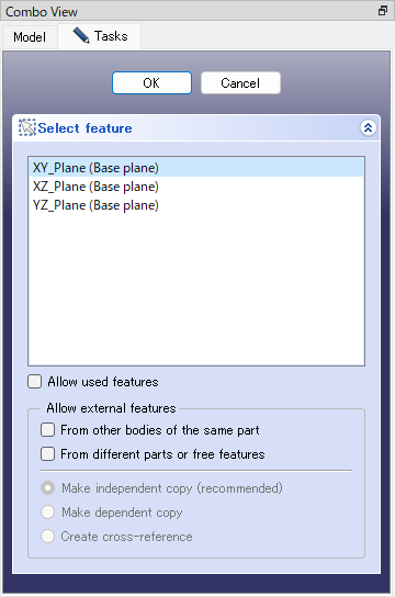
Creates sketch plane -
Select Polyline
 in toolbar and draw a "H" shape on the sketch plane as shown in the following figure.
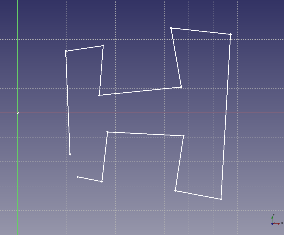
Draws sketch -
Select two end points and select Coincident constraint
 in toolbar to connnect the lines.
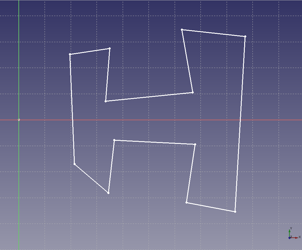
Applies Coincident constraint to the end points -
Select each segment of line and apply constraints as shown in following figure. In this operation, we use Horizonal constraint
 , Vertical constraint
 , Vertical Distance constraint
 , Horizontal Distance constraint
 , Equal Length constraint
 and other constraints.
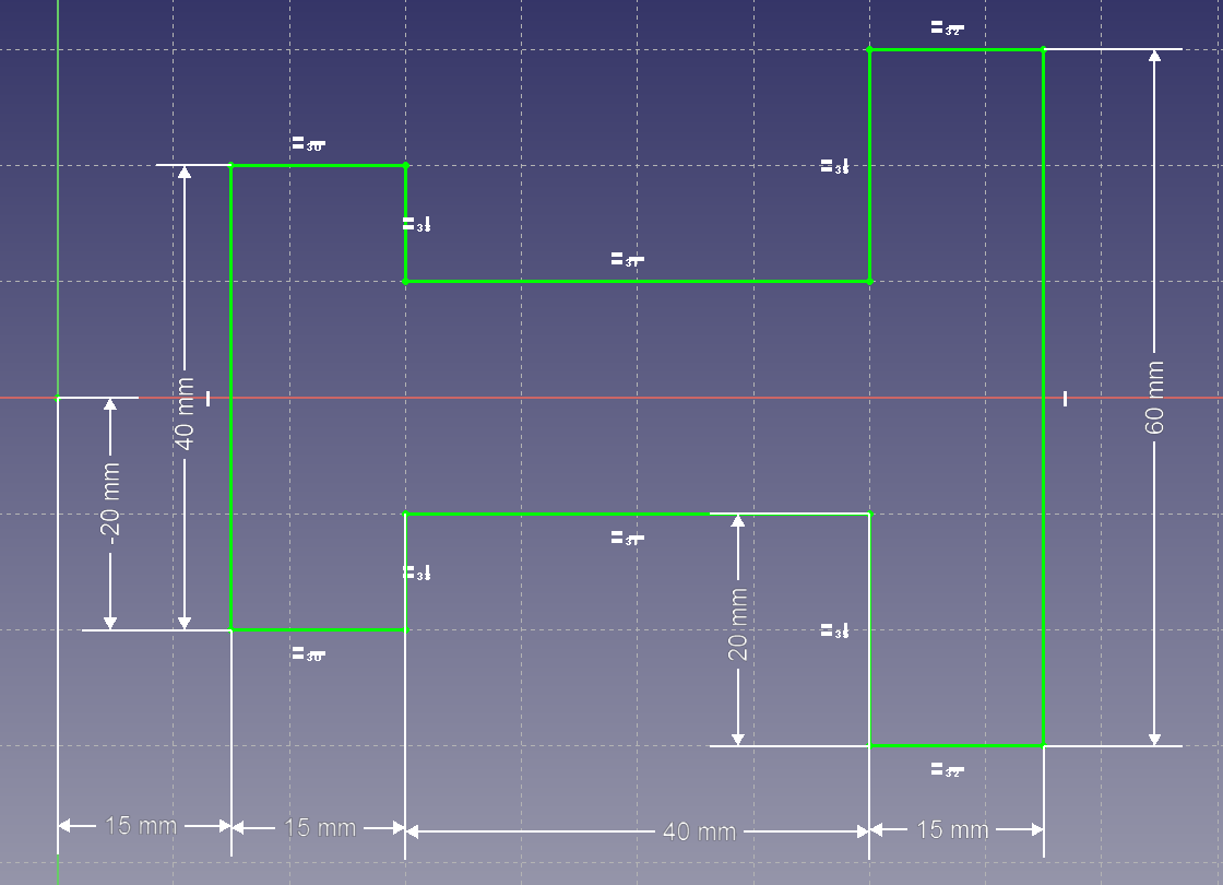
Apply constraints to the sketch Click on Task tab to exit sketch editing mode.
-
Select the created sketch model tree and execute Revolution
 to execute rotation extruding. Enter angle of rotation on the dialog and click .
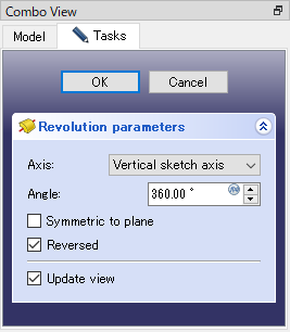
Revolution dialog Rotation axis can be selected from followings.
- Sketch plane's Horizonal axis
- Sketch plane's Vertical axis
- 3d coordinate-system's X axis
- 3d coordinate-system's Y axis
- 3d coordinate-system's Z axis
- Construction line in the sketch (select by click on 3D view)
- Edge of exisiting shape (select by click on 3D view)
Revolution operation results are as follows.
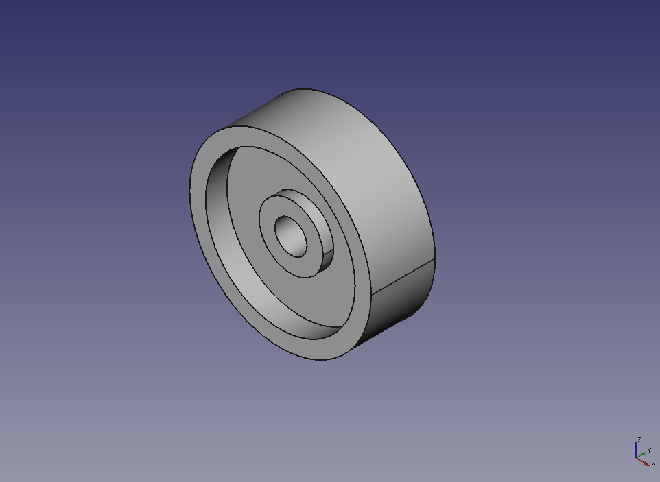
Rotates 360 degree 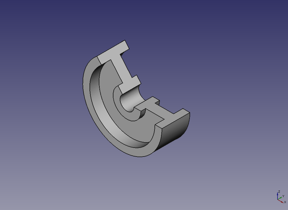
Rotates 230 degree