FreeCAD: How to make gear with Involute Gear tool
Switch workbench to Part Design workbench
 .
.-
Select [Part Design]-[Involute gear...] menu.
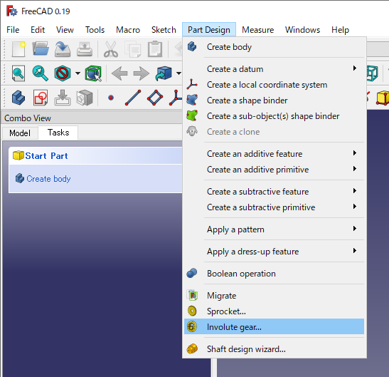
[Part Design]-[Involute gear...] -
Control panel for Involute gear will be displayed in Tasks tab. And a gear with the center (0, 0, 0) and the Z axis as the rotation axis is displayed on the 3D view.
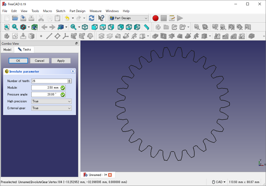
Editing an involute gear You can set following parameters in the control panel. After parameter settings, click OK to finish editing.
Parameter Meaning of the parameter Number of teeth Number of gear's teeth Module The value obtained by dividing the pitch circle diameter by the number of teeth. For example, if a gear has 30mm diameter and 20 teeth, you should set 1.5 (= 30/20) into this parameter. In general, the gears must have same module value to mesh each other. Pressure angle Pressure angle. The angle between the radial line passing through the pitch point and the tangent line of the tooth profile. Heigh precision If True, heigh precision. Other, low precision. External gear If True, external gear. Other, internal gear. Addendum Coefficient The height of the tooth from the pitch circle to the tip, normalized by the module. Dedendum Coefficient The height of the tooth from the pitch circle to the root, normalized by the module. Root Fillet Coefficient Radius of the fillet at the tooth root, normalized by the module. Profile Shift Coefficient Outwards shift coefficient of the gear profile, normalized by module. 
Pitch circle 
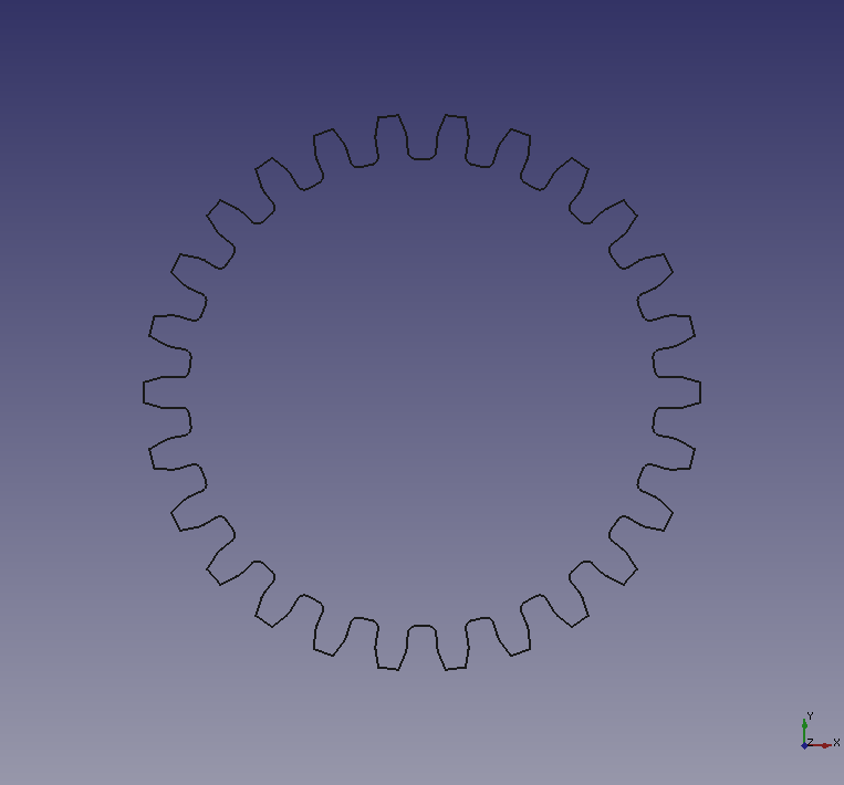
Pressure angle Example of number of teeth

Number of teeth: 26 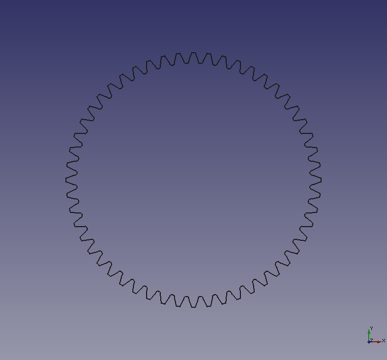
Number of teeth: 52 Example of pressure angle
Pressure angle: 10°
Pressure angle: 20° 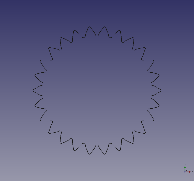
Pressure angle: 30° Example of enable/disable heigh precision
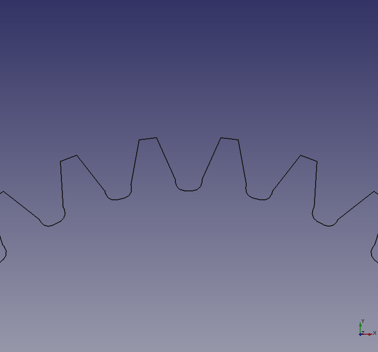
Heigh precision: True 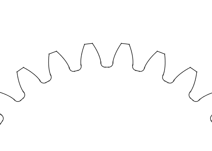
Heigh precision: False Example of enable/disable external gear
External gear: True 
External gear: False -
Gear angle and position can be changed on Data tab. Select the created gear on model tree and edit rotational angle, axis and position on Data tab at bottom of Combo view.
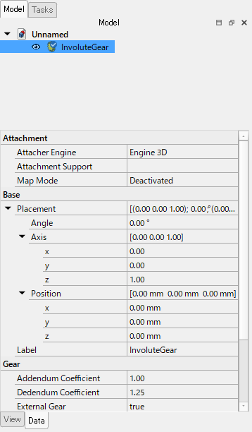
Direction parameters for gear -
To make the gear 3D in Part Design workbench, the gear should be at inside of body. Create new body
 , then Drag the gear on the model tree and place it under the body.
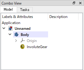
Place the gear under created body -
Select the gear on model tree and extrude
 it. If you want to create internal gear, do boolean operation
 with the extruded gear and another cylinder.
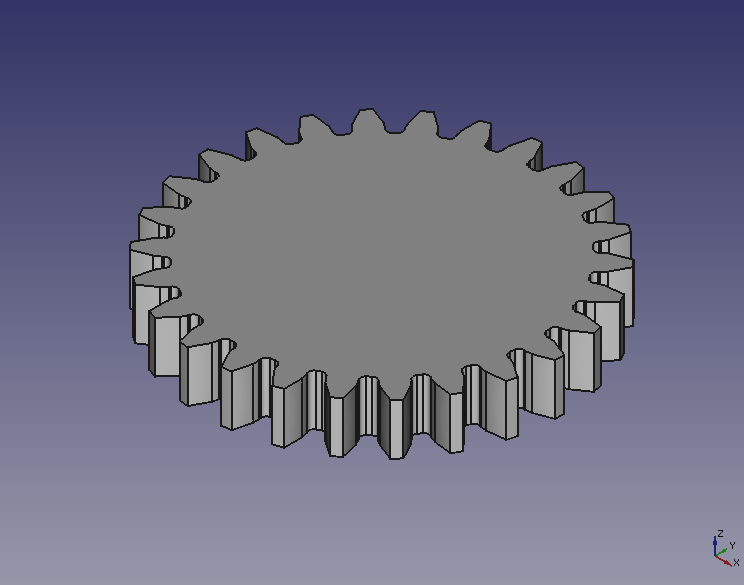
External gear 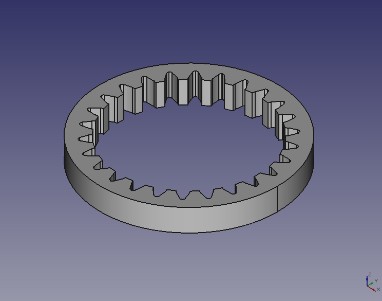
Internal gear