FreeCAD: How to create solids from 2D image?
This section describes how to create a solid from imported image file.

Converting a image from bitmap format to SVG format
If the original image file is in PNG or JPEG format, you must first convert it to SVG format. In the following example, PNG image is converted to SVG image with Inkscape (version 1.02).
-
Start Inkscape and select [File]-[Import...] from the menu. Select an image file in the file dialog to show an import dialog and click button to import the file.
![Fig. Selects [File]-[Import...]](../../HowTo/images/ImageToSolid-Inkscape-Import.png)
Selects [File]-[Import...] 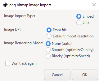
Import dialog (for PNG format file) -
Click the loaded image on window to select it, and select [Path]-[Trace Bitmap...] from the menu. In the displayed "Bitmap Trace" dialog, make sure that "Brightness Boundary" is selected, and then click the button. After conversion, close the dialog with the close button in the upper right corner of the window.
![Fig. Selects [Path]-[Trace Bitmap...]](../../HowTo/images/ImageToSolid-Inkscape-TraceBitmap.png)
Selects [Path]-[Trace Bitmap...] 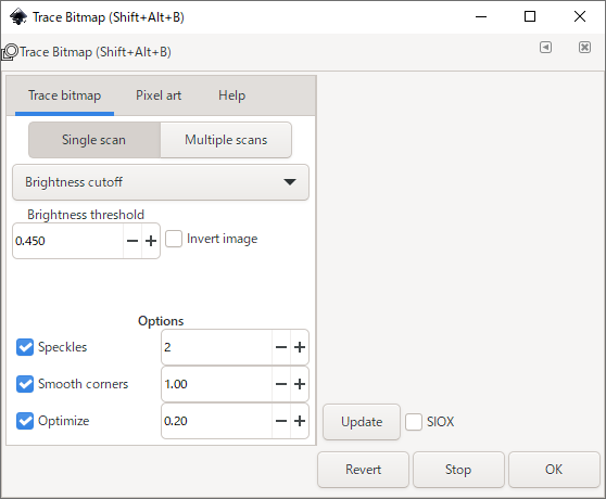
"Trace Bitmap" dialog With these operation, a vector image that overlaps the original image will be generated. Drag the image from the original image and delete the original image.
-
Select [File]-[Save As...] from the menu and save the image as an SVG file.
![Fig. Selects [File]-[Save As...]](../../HowTo/images/ImageToSolid-Inkscape-SaveAs.png)
Selects [File]-[Save As...]
Importing SVG format image and converting it to solids
The SVG format image file is now ready. Then import this file into FreeCAD and convert it to solids.

Start FreeCAD and make new document
 .
.-
Drag&Drop the SVG format file into 3D view to show import dialog. Select "SVG as geometry (importSVG)" and click button to import the file.
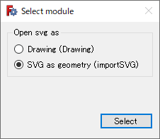
Import dialog for SVG format file 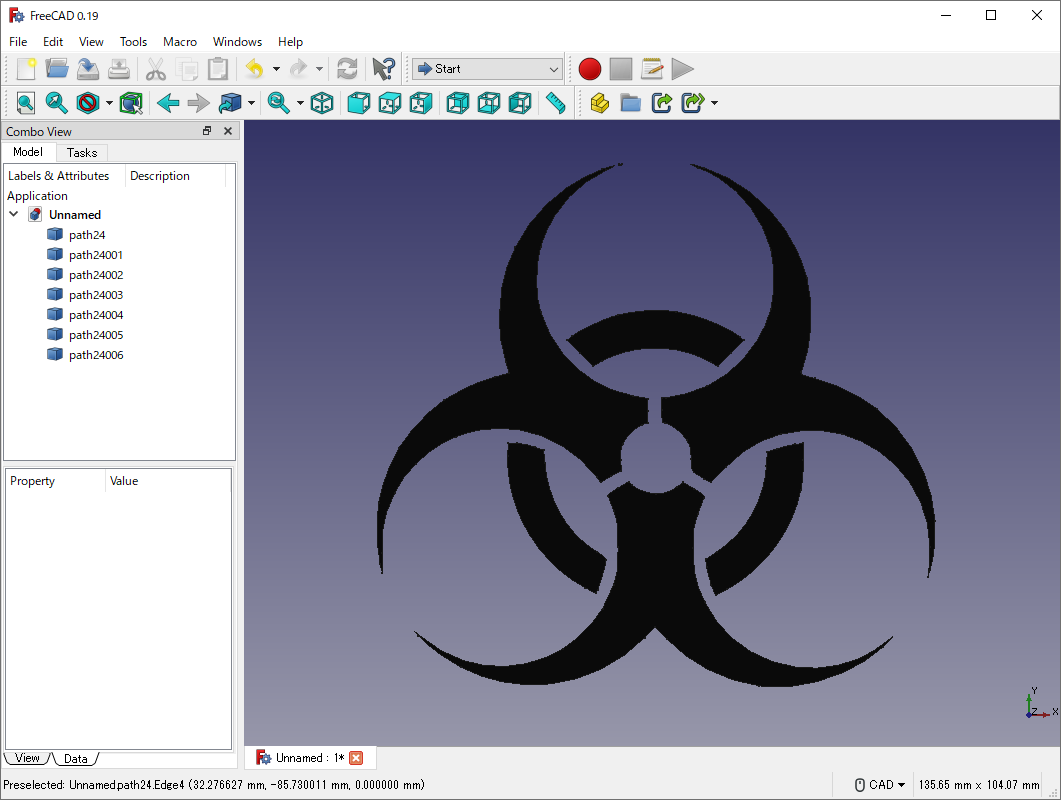
Imported shape -
Switch workbench to Part workbench
 and select all item on model tree and extrude
 them. In the dialog for extruding, select "Custom direction" and set the direction to (0, 0, 1). Then set "Length" to 10 mm and click to extrude.
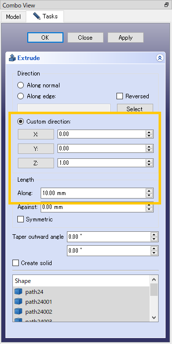
Dialog for extruding 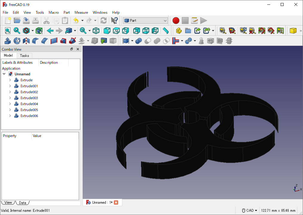
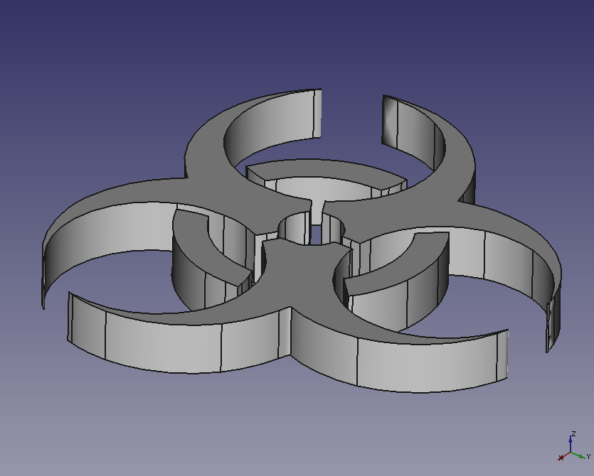
Extrusion result -
We get the created solids into a solid. Select all item on model tree and apply boolean operation (Fuse)
 . Then set shape color to (204, 204, 204) at View tab of Combo view.
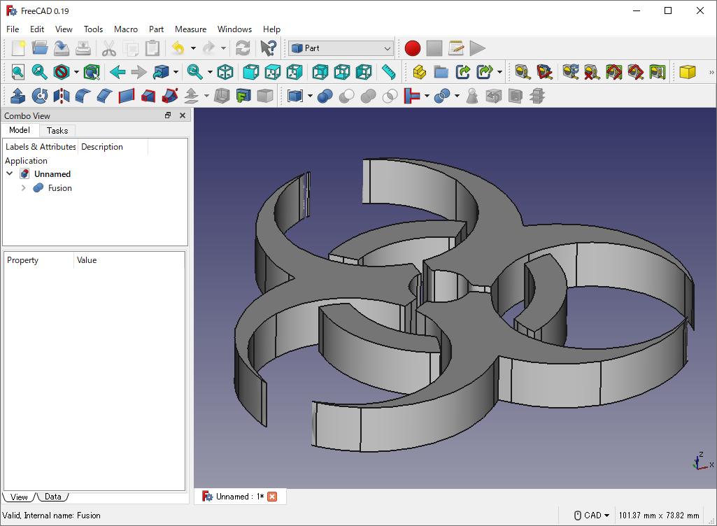
Result of Fuse 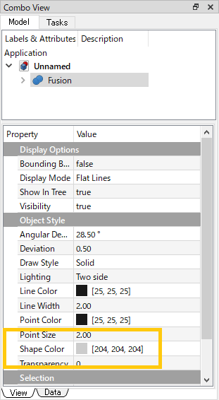
Sets shape color
We have now created solids from the image.