FreeCAD: Sweep with a 3D sketch
Summary
In the Part Design workbench, you can combine multiple sketches with a subshape binder to create a 3D sweep path and it can be used to create a additive pipe
 .
.
Steps
Start FreeCAD and create new document
 .
.Select PartDesign workbench
 .
.-
Create new sketch plane
 and select XY-Plane in shown dialog. Click to create new sketch plane.
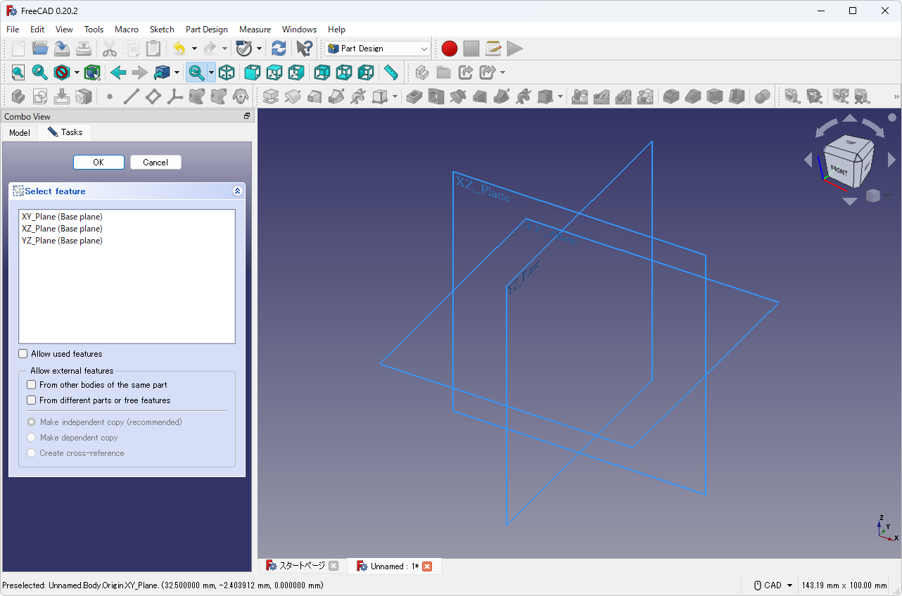
Creates new sketch -
Draw a sketch as shown below with Polyline
 and Fillet
 .
.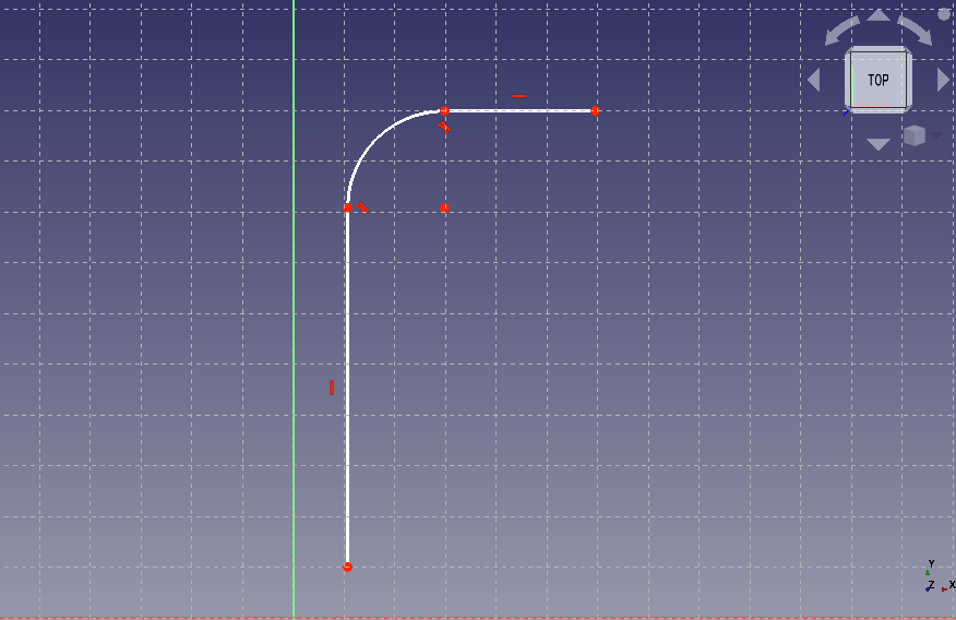
Draws polyline Click at Tasks tab in Combo view to exit sketch editing mode.
-
Select "Origin" in Tree View and push a space key to show it.
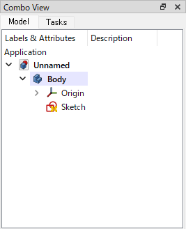
Shows "Origin" (in Tree View) 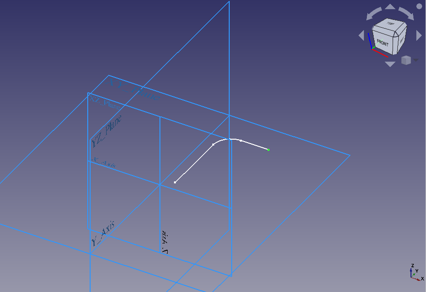
Shows "Origin" (in 3D View) -
Select an end point of the sketch in 3D view and create datum plane
 . Push button and select XZ plane in 3D view.
Click to create a datum plane that parallel to the XZ plane with the sketch endpoint as the origin.

Datum plane parameters 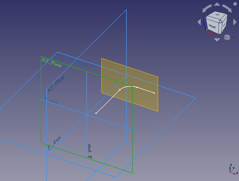
Creates a datum plane -
Select the datum plane in 3D view and create new sketch
on the datum plane.In a similar way as first sketch, draw a sketch with Polyline
and Fillet. Then set an end point of the sketch to the origin of the sketch plane with coincident constraint .
.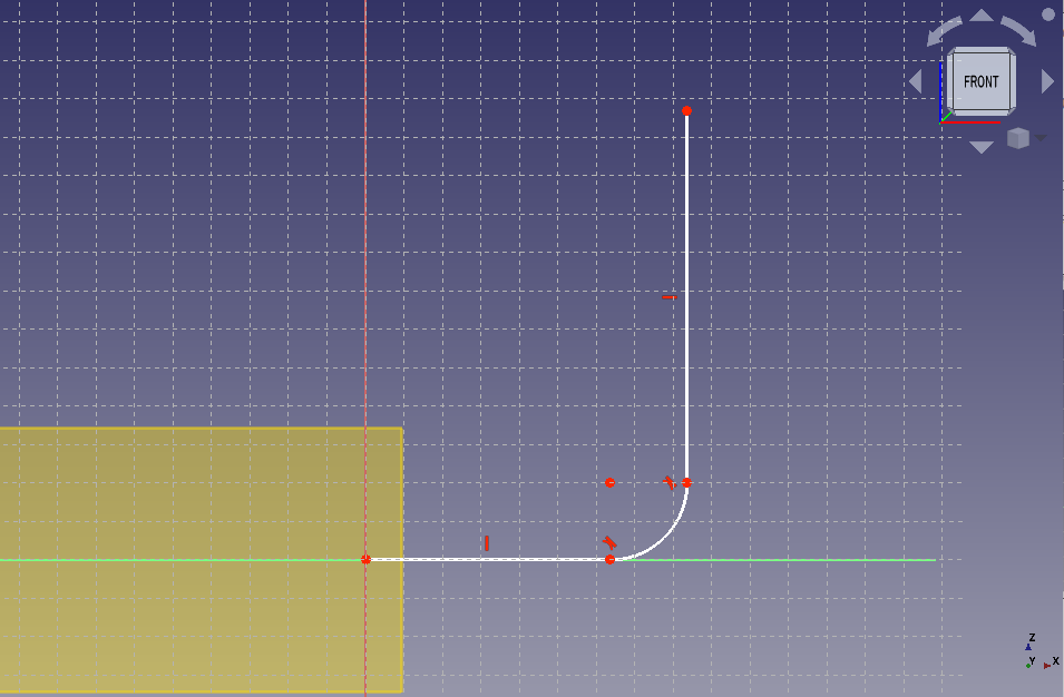
Edits a sketch -
Click at Tasks tab in Combo view to exit sketch editing mode. Now all sketches that will be used as a sweep path have been created.
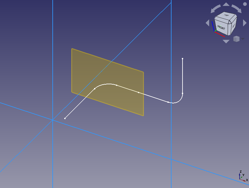
Sketches for a sweep path -
Select the end point of the created sketch and create an another datum plane
. Push button and select XY plane in 3D view. Click to create a datum plane that parallel to the XY plane with the sketch endpoint as the origin.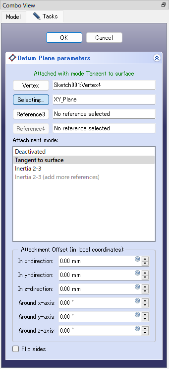
Datum plane parameters 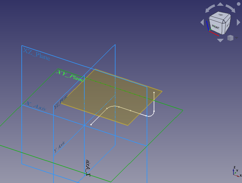
The datum plane -
Select the new datum plane in 3D view and create new sketch
. Then draw a circle centered at the origin. This circle will be used as profile to be swept.
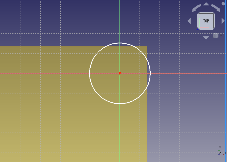
Draws a profile sketch to be swept. Click at Tasks tab in Combo view to exit sketch editing mode.
-
When all the sketches are drawn, it look like as shown below. Since the datum plane will not be used hereafter, select them on Model tree and push space key to hide them.
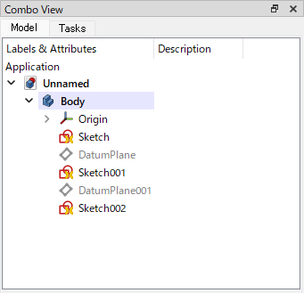
The sketches (on Model tree) 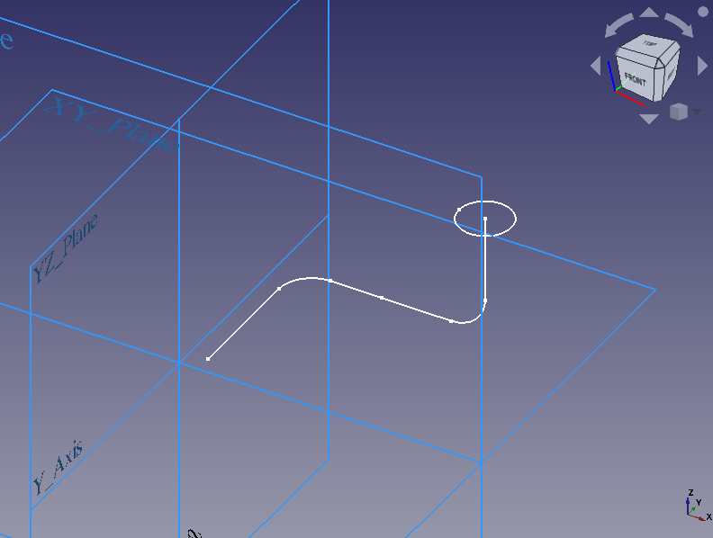
The sketches (in 3D view) -
A sweep path consisting of multiple sketches cannot be swept as is, so it must be combined into one.
While holding down the Ctrl key, select the sweep path sketches "Sketch" and "Sketch001" on the Model tree and create a subshape binder
. Then the sketches will be combined into one subshape binder.After creating the subshape binder, select "Sketch" and "Sketch001" on the Model tree and push space key to hide them.
Now we can sweep the sketches to make solid.
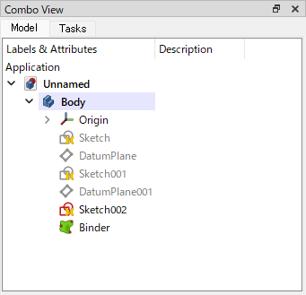
Subshape binder (on Model tree) 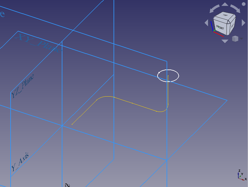
Subshape binder (in 3D view) -
Select "Sketch002", the sketch for the sweep profile on the model tree and create additive pipe
.Confirm that "Sketch002" is set as the profile and Push button in "Path to sweep along" then select subshape binder in 3D view to set it as path to sweep.
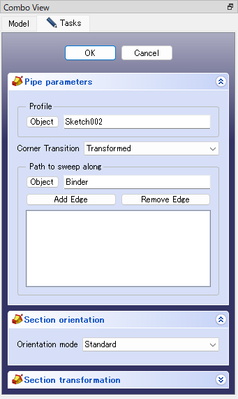
Additive pipe parameters 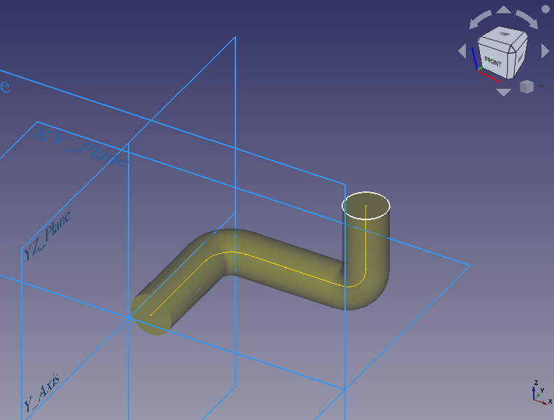
Additive pipe (preview) -
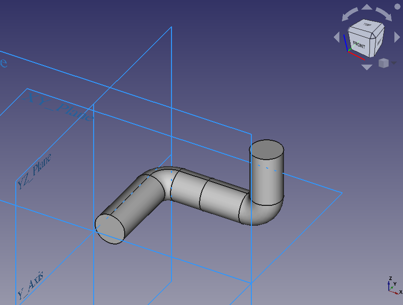
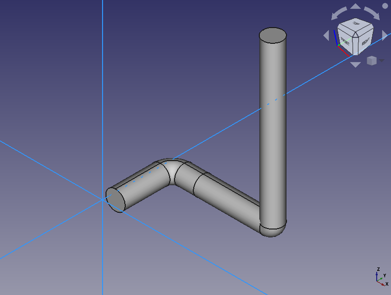
Click at Tasks tab in Combo view to create additive pipe with sweeping.
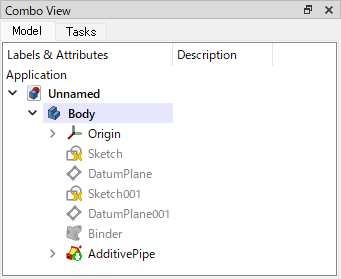
Additive pipe (on Model tree)
Additive pipe (in 3D view) -
After creating the additive pipe, if you re-edit the sketch and change the dimensions of each part, the final shape will be updated according to the change.
Re-edits the sketch to update the shape