Calculation of combustion in the engine cylinder
Case directory
$FOAM_TUTORIALS/combustion/engineFoam/kivaTest
Summary
We calculates the combustion in a piston engine cylinder operating the crank angle from -180° to 60°. The mesh file is prepared in KIVA format and we convert it to OpenFOAM format for using. The model geometry consists of three regions: cylinderHead (green), liner (red), and piston (white) as shown in the figure below.
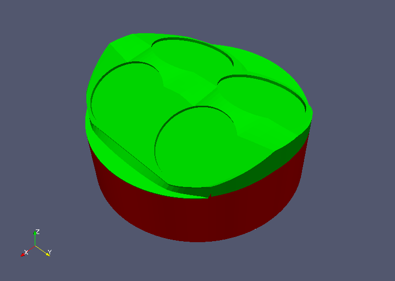 Model geometry (upper)
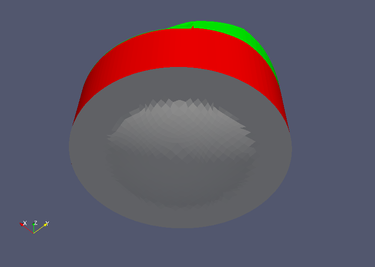 Model geometry (lower)
The engine specifications are defined in the file "constant/engineGeometry" as follows.
engineMesh      layered;
conRodLength    conRodLength [0 1 0 0 0 0 0] 0.147;
bore            bore [0 1 0 0 0 0 0] 0.092;
stroke          stroke [0 1 0 0 0 0 0] 0.08423;
clearance       clearance [0 1 0 0 0 0 0] 0.00115;
rpm             rpm [0 0 -1 0 0 0 0] 1500;
The settings, ignition position, etc. of the equations for combustion reaction are defined in the file "constant/combustionProperties", and the fuel, oxidant, and products of combustion are defined in the file "constant/thermophysicalProperties" as "fuel", "oxidant", and "burntProducts", respectively.
The meshes are as follows, and the number of mesh is 27544.
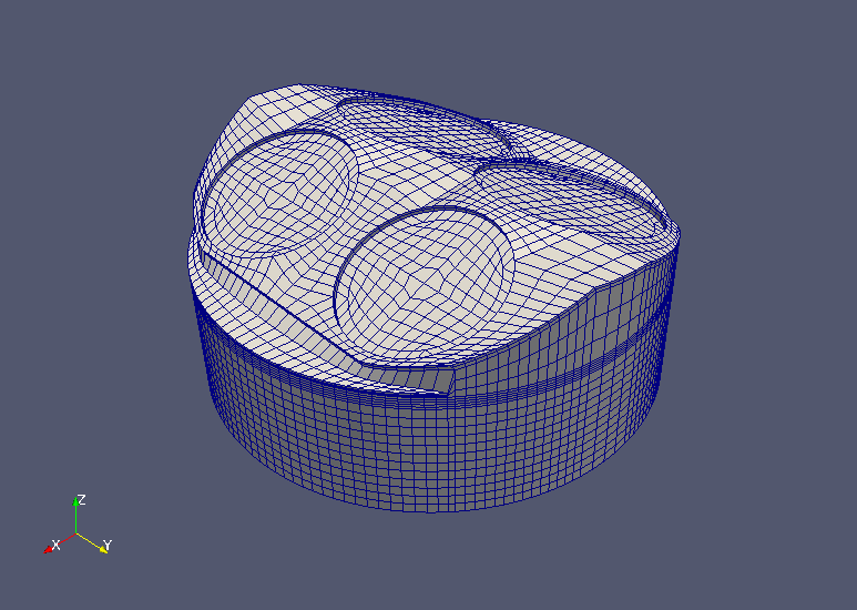 Meshes (upper)
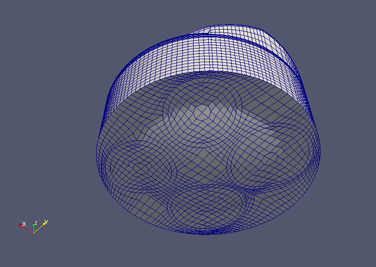 Meshes (lower)
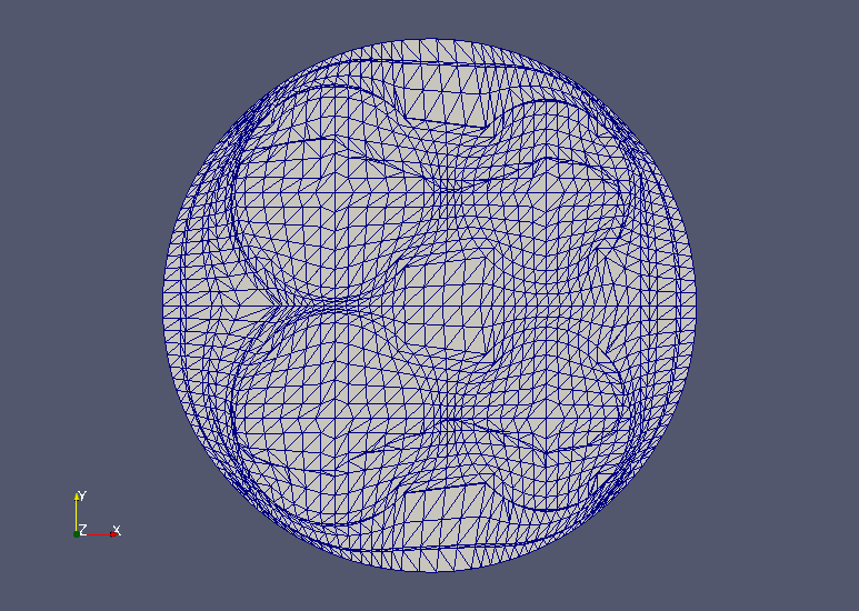 Meshes (XY-plane)
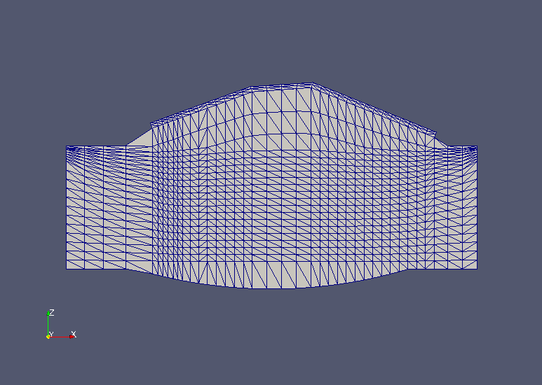 Meshes (XZ-plane)
The calculation result is as follows.
The flow velocity, pressure, and temperature distributions at a crank angle of 60° in the XY plane (Z=0.07) and XZ plane (Y=0) are shown below. A sphere in the figure indicates the ignition position.
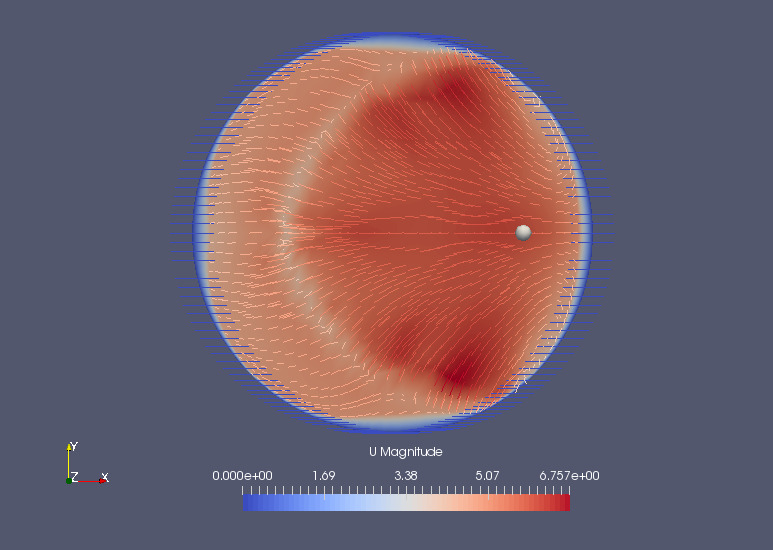 Flow velocity at Z=0.07 plane (U)
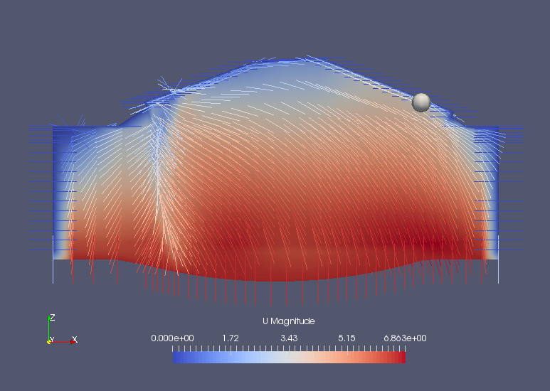 Flow velocity at Y=0 plane (U)
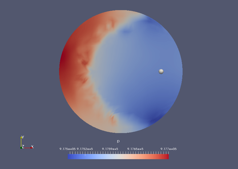 Pressure at Z=0.07 plane (p)
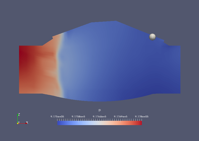 Pressure at Y=0 plane (p)
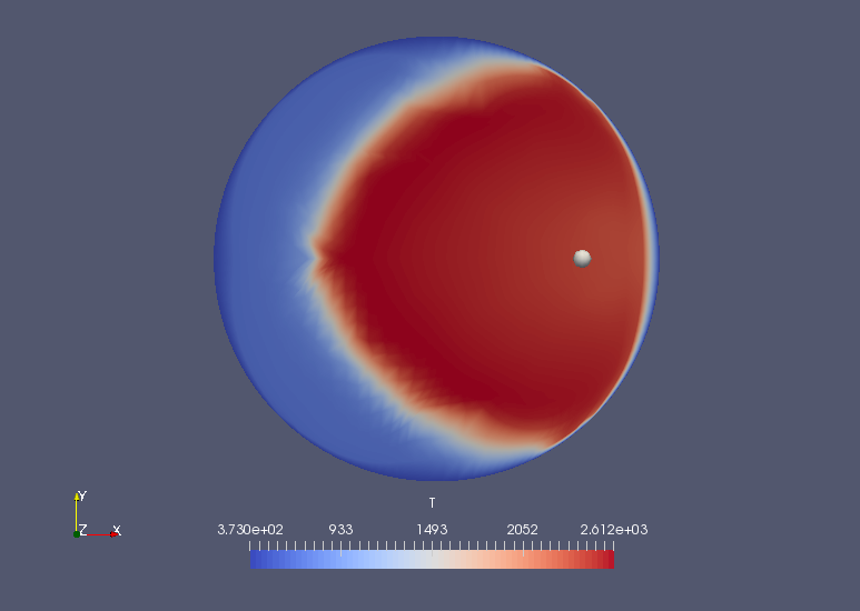 Temperature at Z=0.07 plane (T)
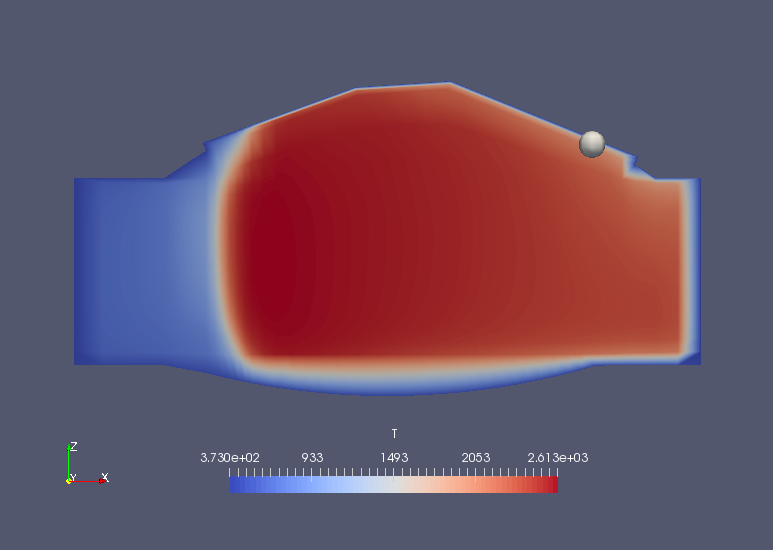 Temperature at Y=0 plane (T)
And the average pressure and temperature at each crank angle are output to The file "logSummary.-180.dat".
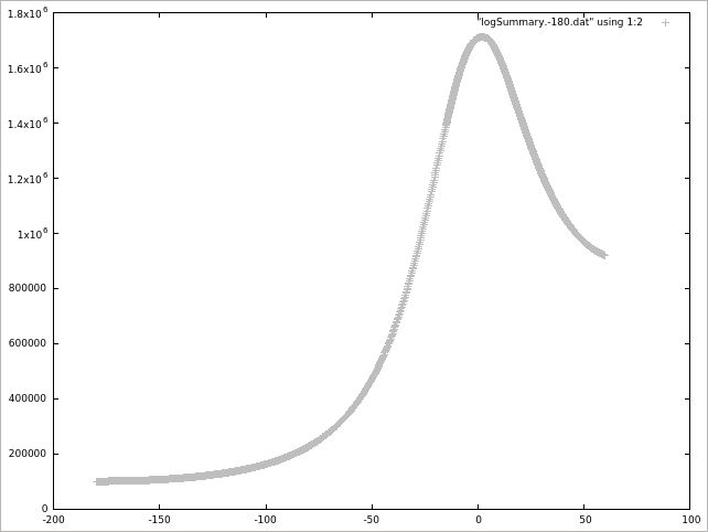 Average pressure (p)
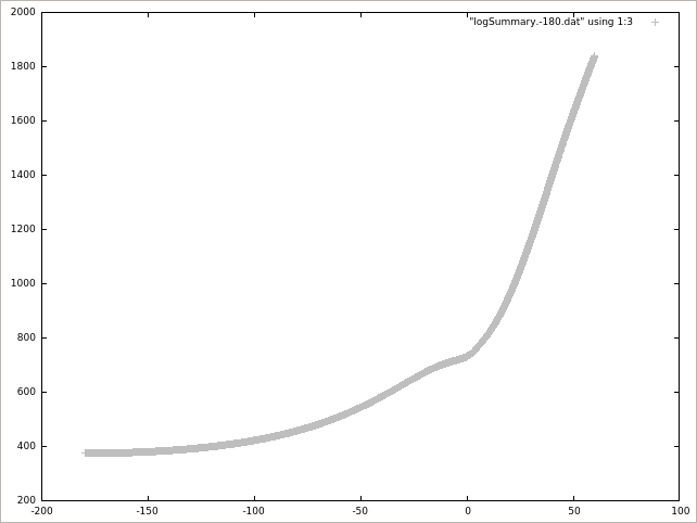 Average temperature (T)
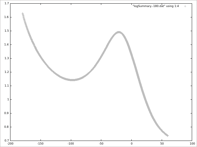 Average of (k * 2/3)1/2
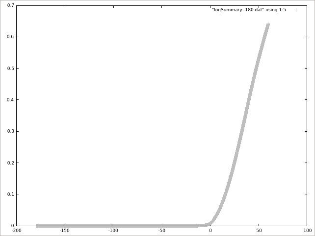 1 - (Average of b)
Commands
cd kivaTest
kivaToFoam -file otape17
engineFoam
paraFoam
gnuplot
gnuplot>plot "logSummary.-180.dat" using 1:2 lc rgb "gray"
gnuplot>plot "logSummary.-180.dat" using 1:3 lc rgb "gray"
gnuplot>plot "logSummary.-180.dat" using 1:4 lc rgb "gray"
gnuplot>plot "logSummary.-180.dat" using 1:5 lc rgb "gray"
We use the utility "kivaToFoam" to convert the KIVA format (KIVA-3V format) mesh file "otape17" into OpenFOAM format.
Calculation time
21 minutes 33.99 seconds *Single, Inter(R) Core(TM) i7-2600 CPU @ 3.40GHz 3.40GHz
Reference
- OpenFOAM-4.x/applications/solvers/combustion/XiFoam/XiFoam.C
- "Numerical Study of the b-Ξ Flame Wrinkling Combustion Model in Oracles Test Rig", J. Aerosp. Technol. Manag. vol.7 no.4 São José dos Campos Oct./Dec. 2015, Guilherme Henrique Santos, Wladimyr Dourado(PDF)
- "Tutorial XiFoam - Version: OpenFOAM-1.7.x", 2010/11/4, Ehsan Yasari(PDF)
- OpenFOAM-4.x/applications/solvers/combustion/engineFoam/logSummary.H