FreeCAD: How to project a shape onto a curve surface?
In this section, we explain how to project a surface or edge onto a curved surface to create a new shape. This function allows you to create a shape by projecting text, images, etc. onto a curved surface.
Steps
-
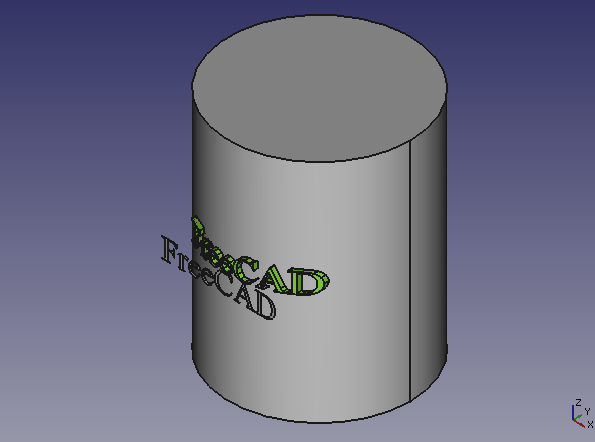
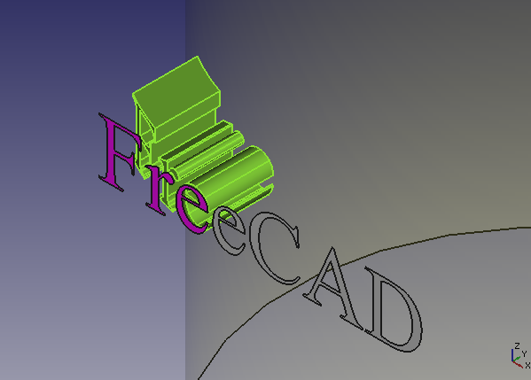
At first, we should prepare the shape to be projected and the curved surface shape to be projected. In this example, we use a string shape created by Shape String
 as the projected shape (refer to "How to create character string shape solids?").
Shape to be projected and projection surface -
Run Projection on Surface
 to show a dialog for projection.
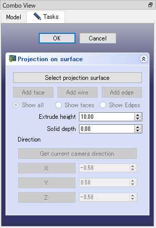
Dialog for projection -
Push button and select projection surface in 3D view. When we select the projection surface, the shpe including the surface will be displayed translucently.
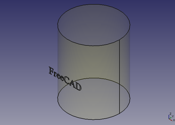
Projection surface setting -
Then we set projection direction. If we push button, the current camera direction in the 3D view will be set as the projection direction. Or if we push , or button, each X, Y, or Z direction will be set as the projection direction.
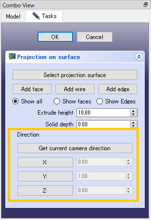
Projection direction setting -
Then we set shapes to be projected. Push button and select faces to be projected. If you want to deselect a face in the projected shape, select the face again in 3D view. When you select all faces, press the button again to exit the setting.
Adding faces If you use button or button, you can set edges as shape to be projected.
Adding edges -
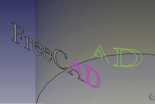
Select the projection method from "Show all", "Show faces", and "Show Edges". The result of each projection is shown below.
"Show all": Projection as solids 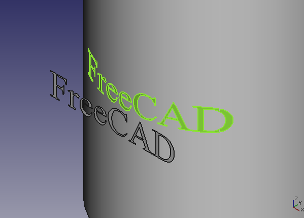
"Show faces": Projection as faces 
"Show Edges": Projection as edges -
Finally, set the extrusion parameters. The parameters are as followings.
Extrusion parameters Parameters description Extrude heigh Extrude length in projection. This parameter will be ignored in projection as wire or edges. Solid depth The amount of translation of the projected result shape from the projection surface. 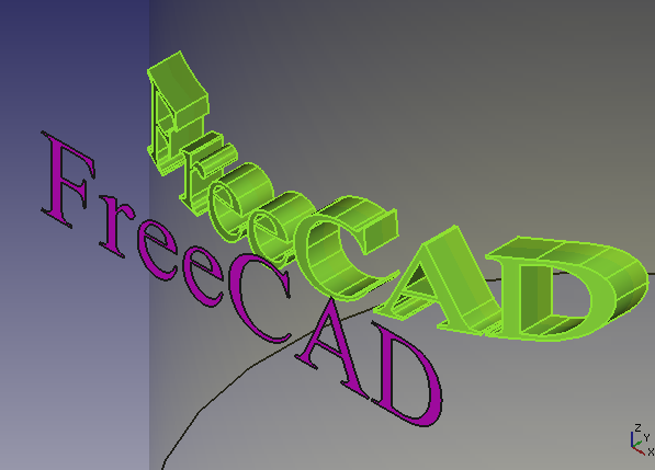
Configuring extrusion parameters -
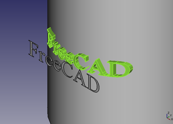
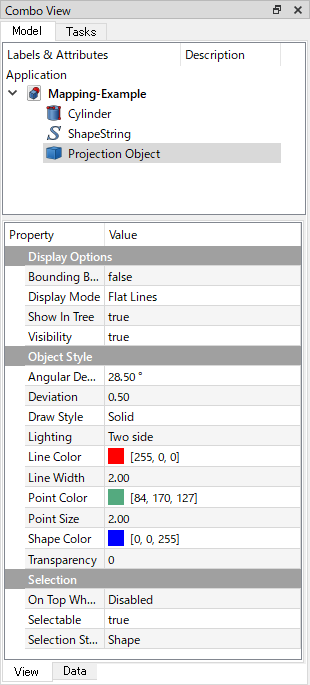
After the parameter settings, click to create projection result shape. If you want to change color of the result shape, select the shape in model tree and change "Line Color", "Point Color" and "Shape Color" properties at View tab.
Changing the colors at View tab 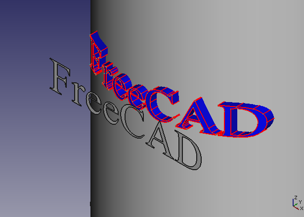
Result of changing the colors The projection result shape will be a different solid from the shape of the projection surface. Do boolean operations such as fuse
 or cut
 as necessary.