FreeCAD: Stress Analysis (1/3)
Summary
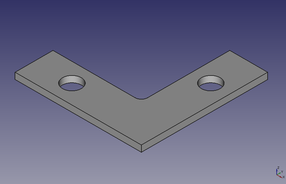
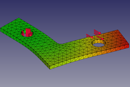
In this tutorial, we will do static analysis for loaded L-shape joint and get it's deformation and stress. Then we will change the shape parametrically to improve the result.
Creating the shape
-
Creating new document
Start FreeCAD and create new document
 .
. -
Creating new sketch plane
Switch workbench to Part Design workbench
 .
.Create new sktch plane
 and select XY-plane on the dialog. Then click .
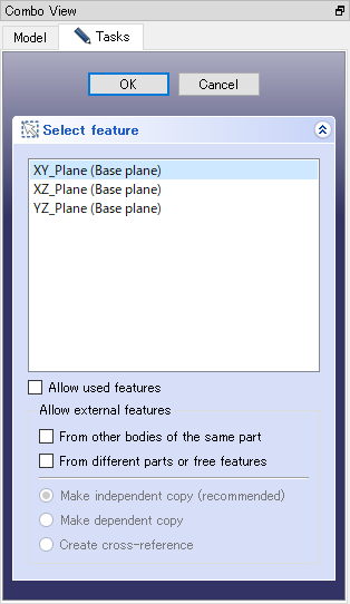
Creating new sktch dialog -
Drawing the sketch
Select polyline
 and draw rough sketch for the joint.
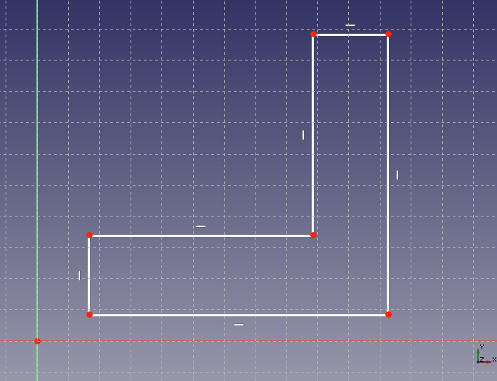
Drawing rough sketch With holizontal distance constraint
 and vertical distance constraint
 , set the length and width to 100 mm and 30 mm, respectively, as shown in the figure below.
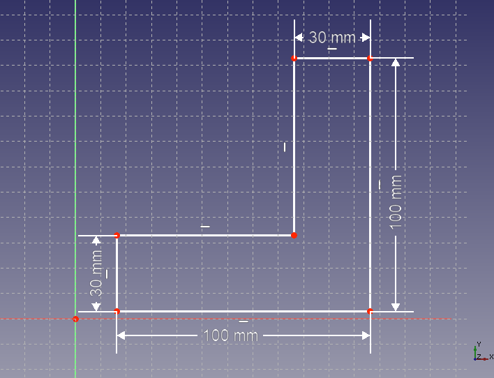
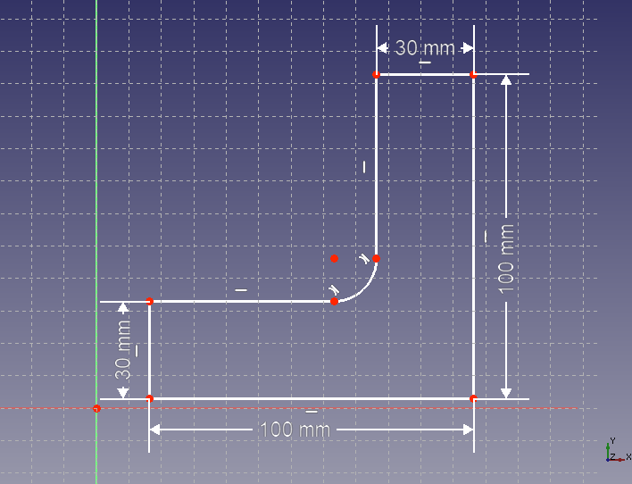
Constrainting the distances Round the corner of the L-shape with fillet
 .
.
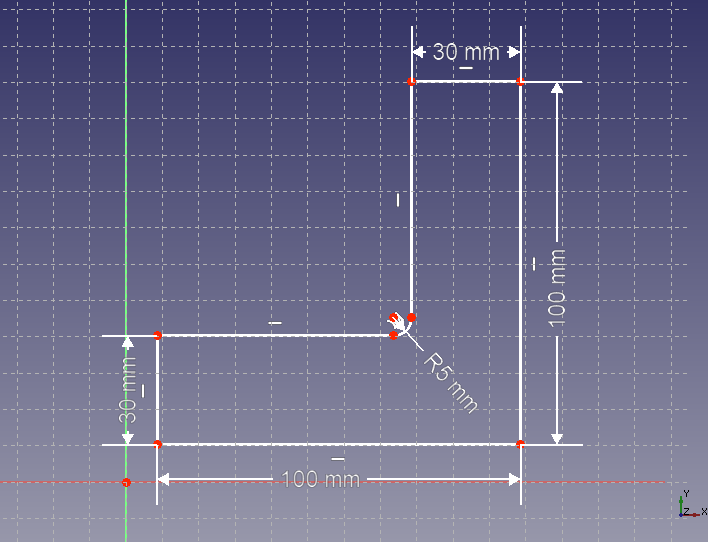
Round the corner Select the rounded corner and set the radius to 5 mm with radius constraint
 .
.
Constrainting the radius Create 2 circles
 for screw hole. Set the radius to 7.5 mm with radius constraint and the center position of the circle as shown in the figure below, with holizontal distance constraint and vertical distance constraint.
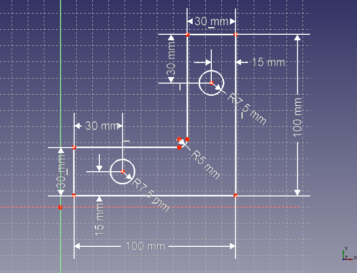
Creating circles for screw hole Match the sketch plane origin with the point at the bottom left of the sketch with point-on-point constraint
 . So the sketch will be draw with green line because it is fully constrained. Then click on task tab to finish sketch editing.
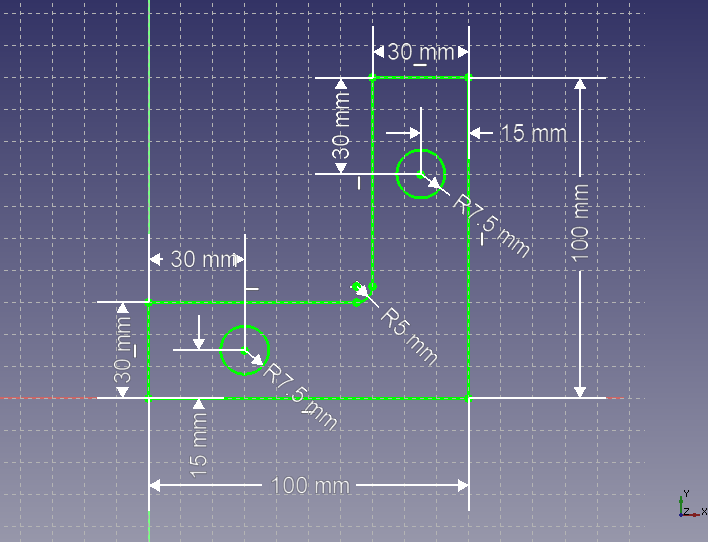
Fully constrained sketch -
Extruding the sketch
Using padding
 , extrude the created sketch with an extrusion dimension of 5 mm to create the shape to be analyzed.
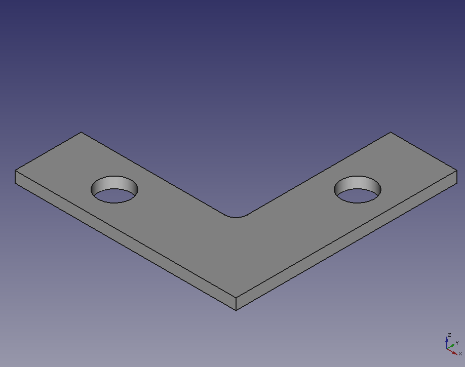
The shape to be analyzed.
The next step is to set up the analysis.