FreeCAD: Tutorial Mug (2/3)
Creating a handle
Then we will create a handle of the mug.
-
Creating a sketch plane for the handle shape.
create a new sketch plane
 and select XZ-Plane in the dialog. Click to create sketch plane.
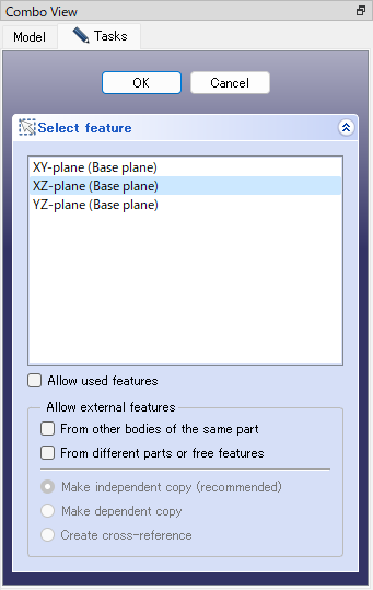
"New sketch plane" dialog -
Drawing the handle shape
Select the polyline
 and click 4 points to draw a sketch of a handle. Click mouse right button to finish drawing.
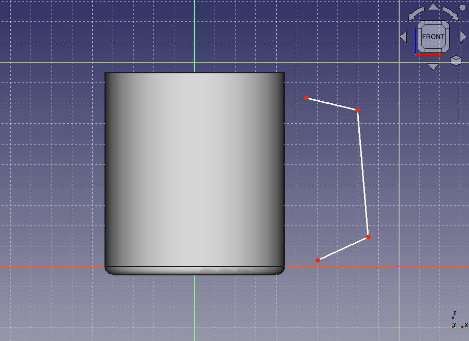
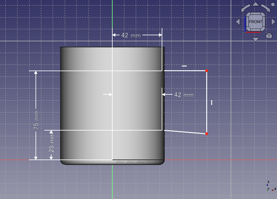
Drawing a sketch of a handle Click an end point of the polyline on the top side and execute lock constraint
 . Type (42mm , 75mm) as the coordinate.
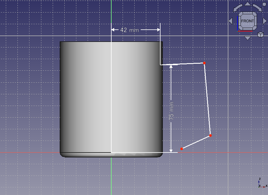
Constraining the coordinate of end point on the top side Similarly, click an end point of the polyline on the bottom side and execute lock constraint
. Type (42mm , 25mm) as the coordinate.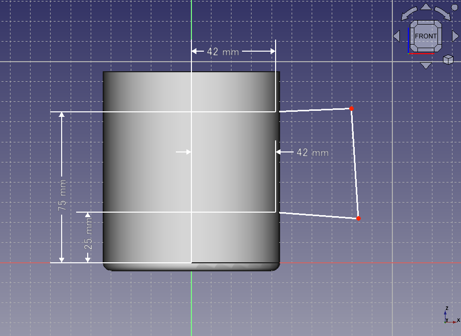
Constraining the coordinate of end point on the bottom side Select the edge of polyline on the top side and constrain to horizontal
 . And select the edge of polyline on the right side and constrain to vertical
 .
.
Constraining the edges to horizontal/vertical Select fillet
 and click 2 edges of a corner to create fillet. Create fillets on both corners and click mouse right button to finish the operation.
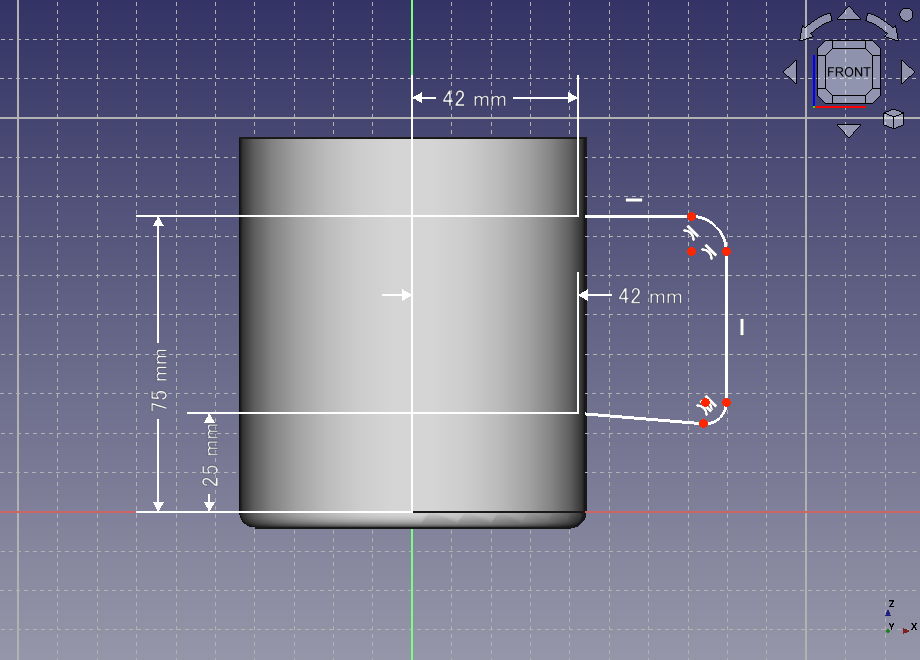
Creating fillet Select the edge on top side and execute horizontal dimension constraint
 to constrain the dimension to 30 mm. Similarly, select the edge on right side and execute verical dimension constraint
 to constrain the dimension to 25 mm.
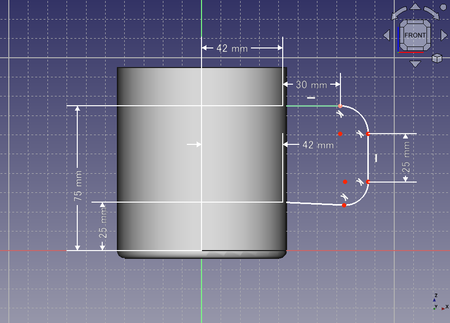
Constraining the horizontal/vertical dimension Select fillet of each corner and execute radius constraint
 to constrain a corner radius to 10 mm.
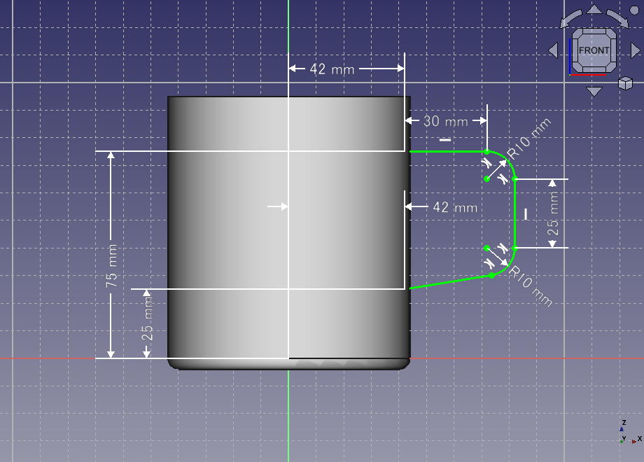
Constraining corner radii When both corner radii were constrained, the sketch will be fully contained and be displayed with green lines. Then click on Task tab to finish sketch edit.
-
Creating a sketch plane for a profile of the handle
Select the vertical edge of the created sketch in the 3D view and make a datum plane
 . A datum plane is an imaginary plane that can be used as a reference plane.
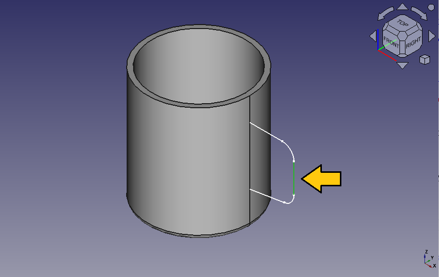
Selects the edge of the sketch Make sure that "Normal to edge" is selected for Attach Mode in the dialog and click to make a datum plane.
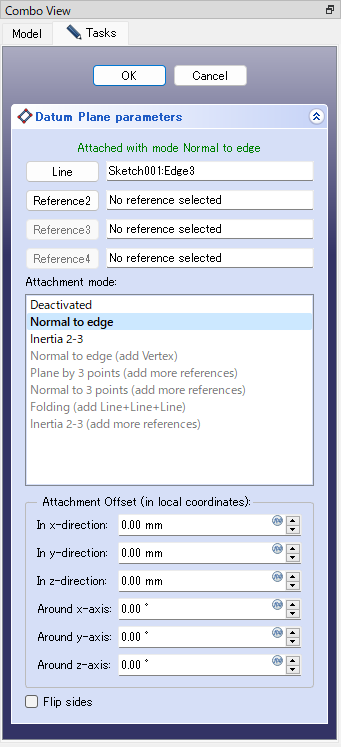
Datum plane parameters 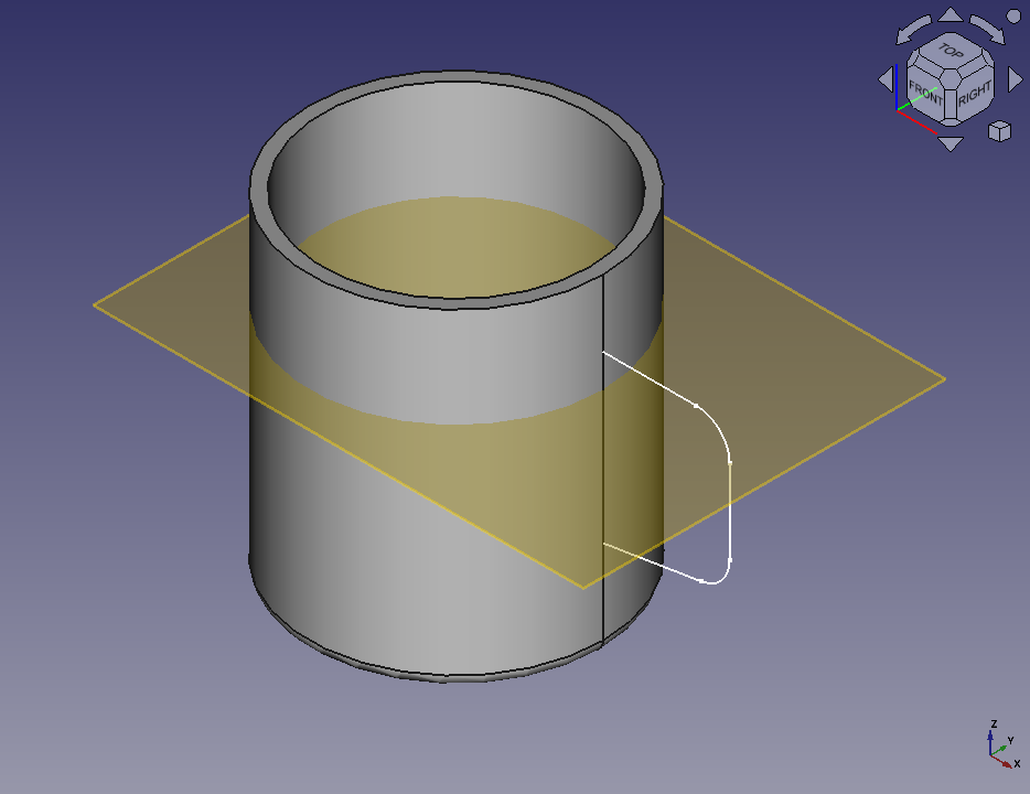
The datum plane Select the created datum plane in the 3D view and make a new sketch
to make a new sketch on the datum plane.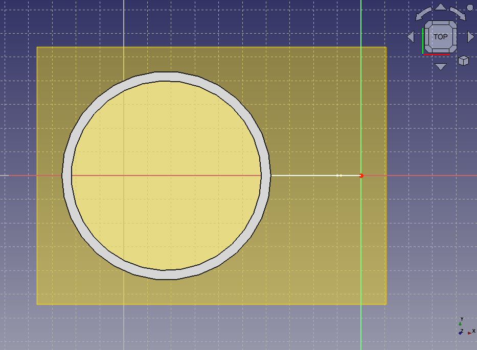
New sketch on the datum plane -
Drawing a sketch of the handle profile
Select slot
 and select 2 points to draw a slot.
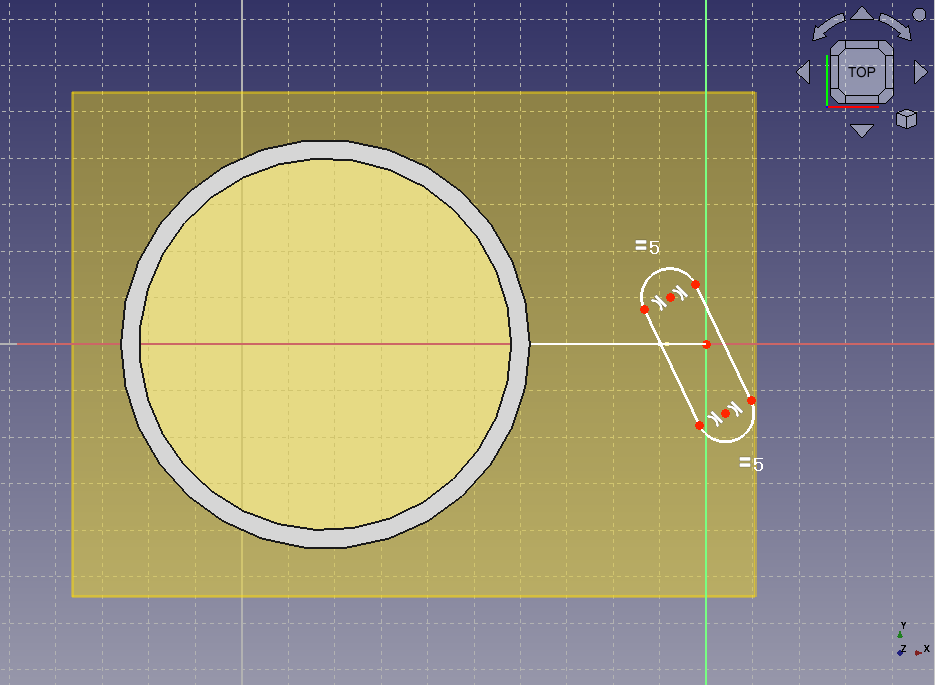
Drawing a slot Select 2 centers of the slot and horizontal axis of the sketch plane then execute symmetric constraint
 . So the centers of the slot will be constrained symmetrical with the horizontal axis as a line of symmetry.
Symmetric constraint Select the top side arc of the slot and constarin the radius
to 5 mm.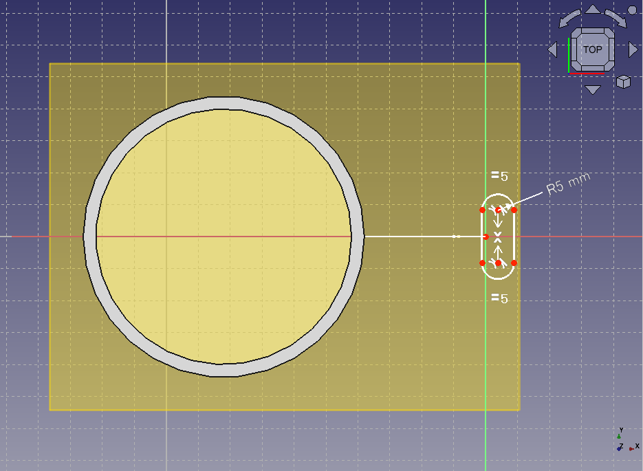
>Constraining radius Select a upper left point of the sketch and execute lock constarint
to constarin the coordinate to (-5mm , 2.5mm).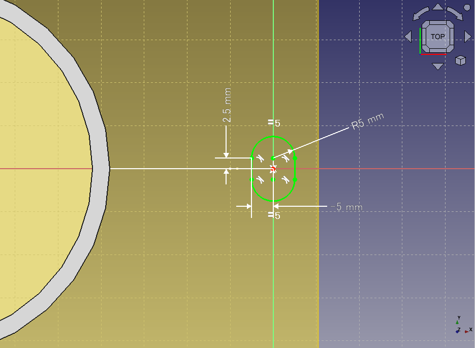
Constraining the coordinate The sketch will be fully contained and be displayed with green lines. Then click on Task tab to finish sketch edit.
So the sketch of the handle profile has beeen drawn.
Sketch of the handle profile -
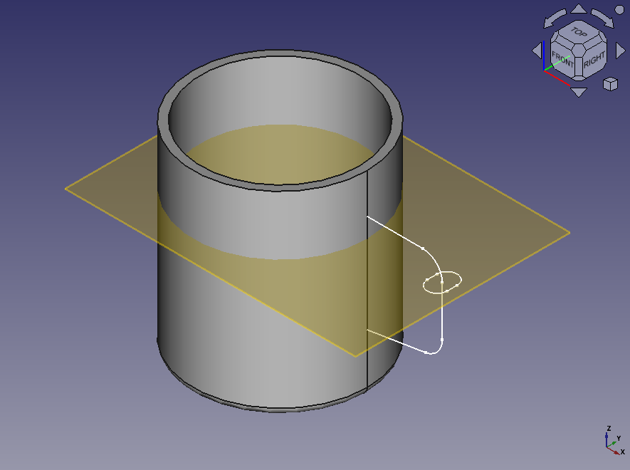
Sweeping the profile of handle to create solid
Select the profile sketch (Sketch002) in model tree and execute Additive Pipe (sweeping)
 to show the dialog.
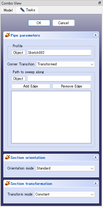
Dialog for sweeping Click button below "Path to sweep along" and select the sweep path sketch (Sketch001) on 3D view. Sweeping result will be shown on 3D view. Click to execute sweeping operation.
The datum plane will not be used in following, so select "DatumPlane" on the model tree and press the space key to hide it.
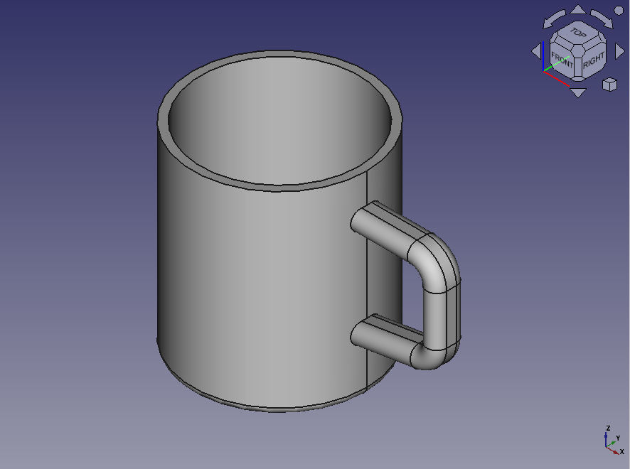
Sweeping results