FreeCAD: How to create meshes from a solid?
-
Create new document
 and create a shape to be meshed.
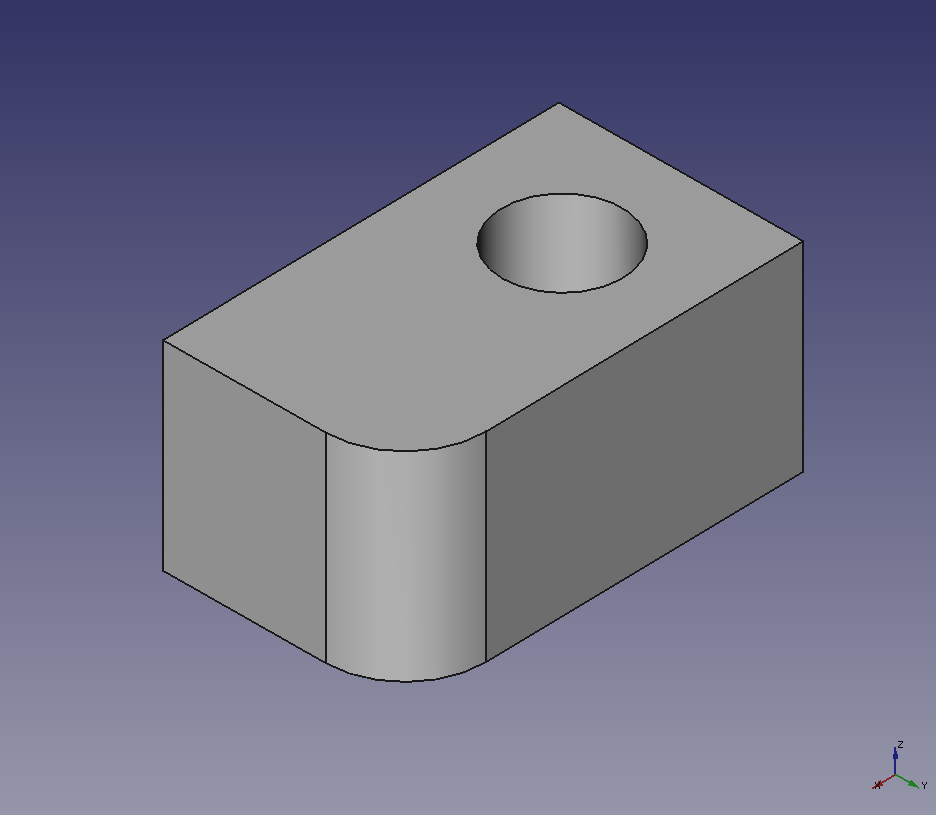
Creates a shape Switch workbench to Mesh Design wrokbench
 .
.-
Select the shape in model tree and run "Mesh from shape"
 to show a dialog box as following. Then select the mesher in the tabs of the dialog box and set each parameter.
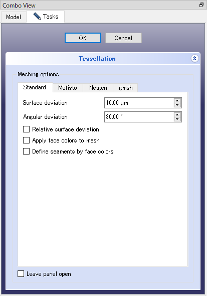
Dialog box for Tessellation Mesher that can be used are "Standard", "Mefisto", "Netgen" and "gmsh". Meshes to be created and the parameters of each mesher are as follow.
-
Standard
Parameter Behavior Surface deviation If this parameter is smaller, meshes becomes finer. Angular deviation If this parameter is smaller, meshes becomes finer. Relative surface deviation Create meshes depending on edge length. Apply face colors to mesh Set shape color to the mesh. Define segments by face color Set segments to meshes depending on shape colors. 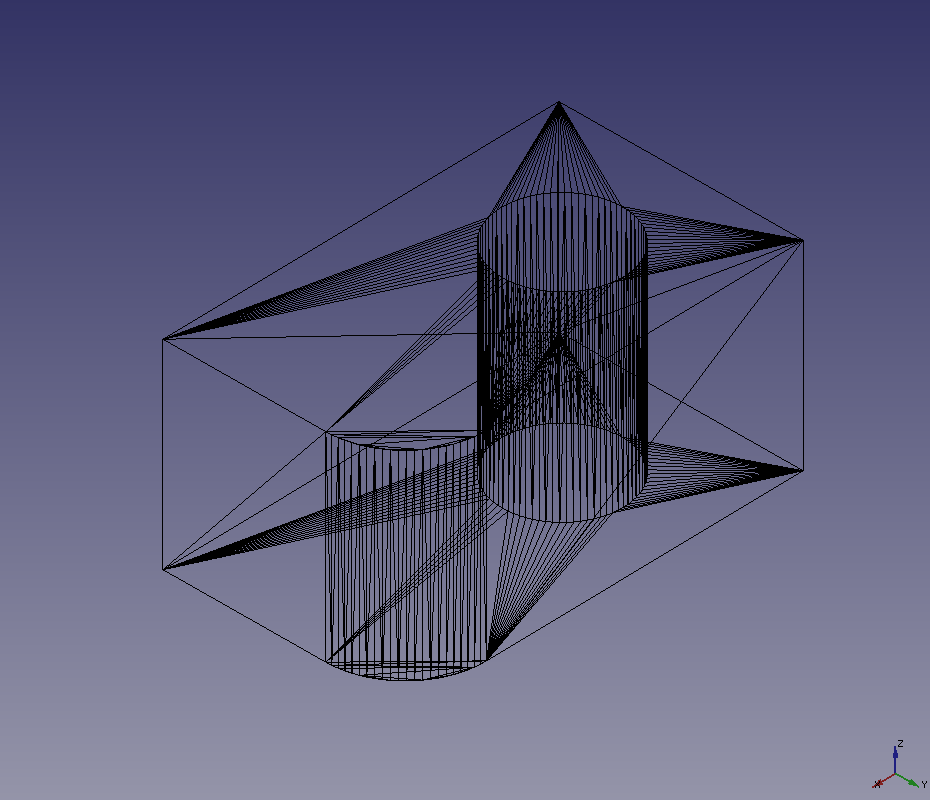
Surface deviation=0.1 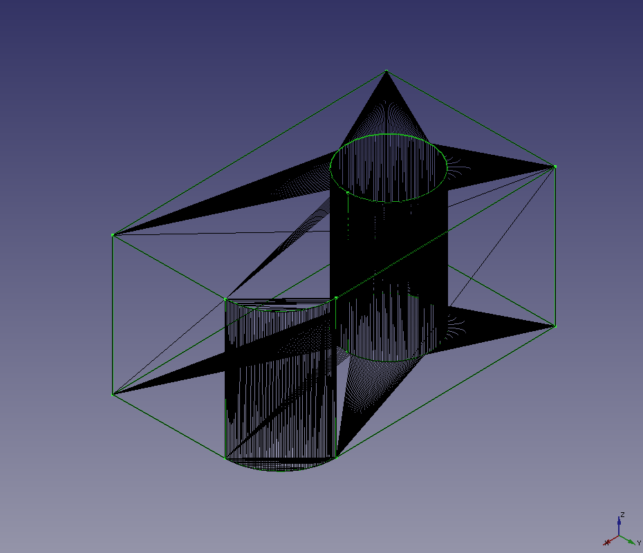
Surface deviation=0.01 -
Mefisto
Parameter Behavior Maximum Edge length Maximum edge length. If this parameter is smaller, meshes becomes finer. 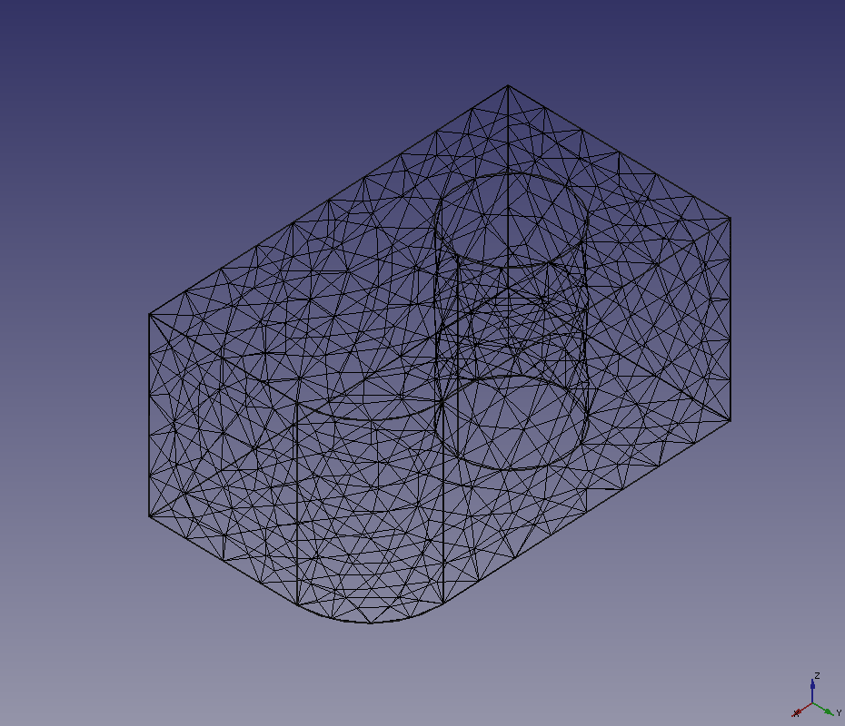
Maximum Edge length=10.0 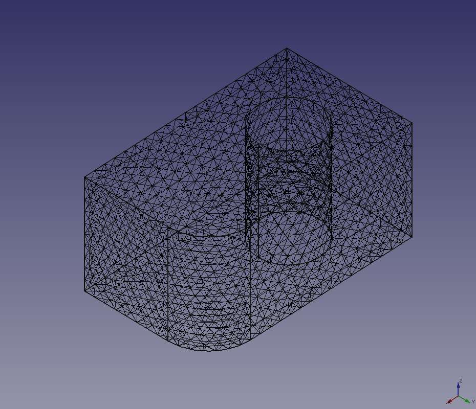
Maximum Edge length=5.0 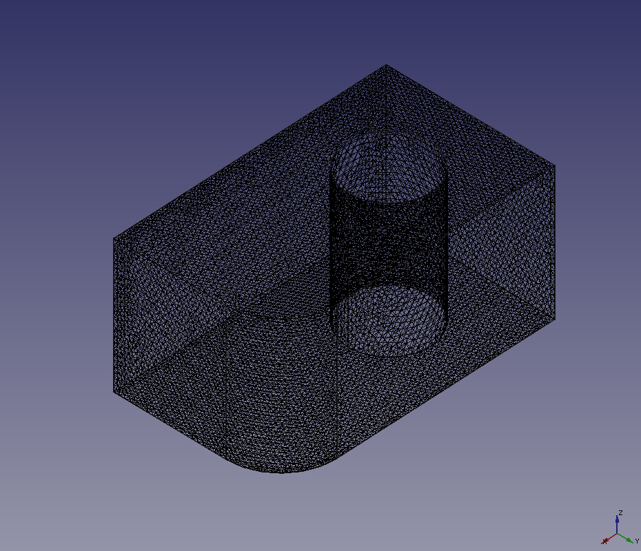
Maximum Edge length=2.0 -
Netgen
Parameter Behavior Fineness Degree of mesh fineness. If you want to customize parameters, select "User defined". Mesh size grading If this parameter is smaller, meshes becomes finer. A value in the range of 0.1-1. Element per edge If this parameter is larger, meshes becomes finer. A value in the range of 0.1-1. Element per curvature radius If this parameter is larger, meshes becomes finer. A value in the range of 0.2-10. Optimize surface Whether optimization of surface shape will be done. Second order elements Whether second order elments will be generated. Quad dominant Whether meshes will be arranged like hexahedral. 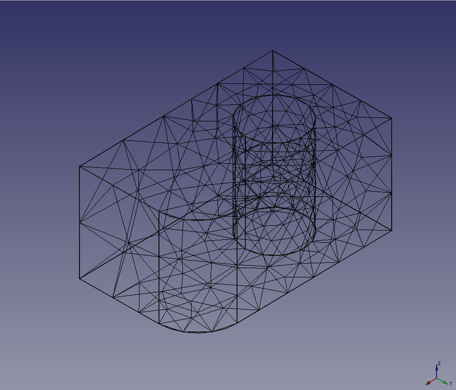
Mesh size grading=0.3
Element per edge=1.0
Element per curvature radius=2.0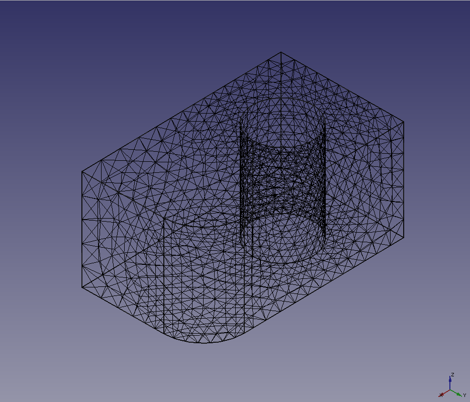
Mesh size grading=0.1
Element per edge=3.0
Element per curvature radius=5.0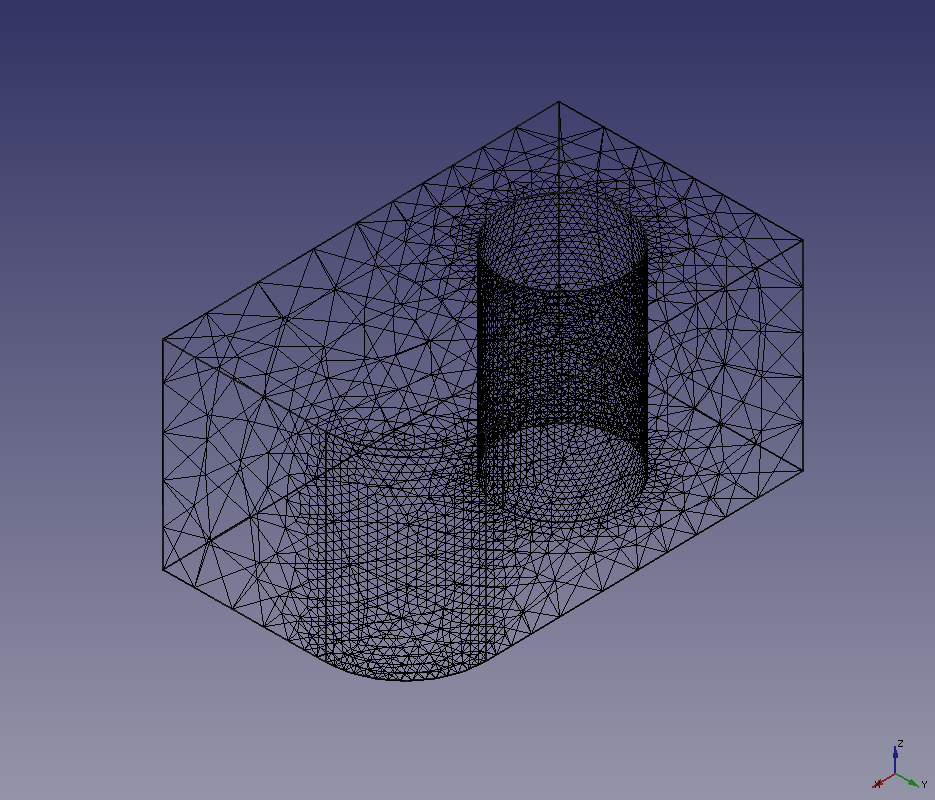
Mesh size grading=0.3
Element per edge=5.0
Element per curvature radius=10.0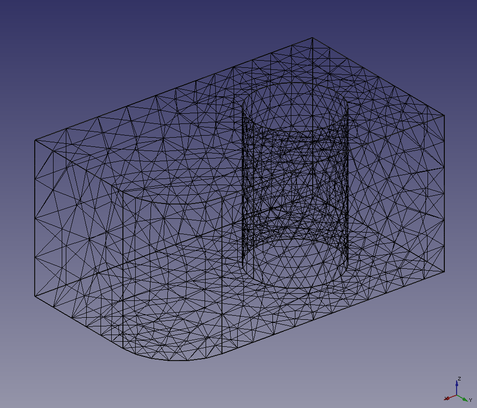
Enable second order elements 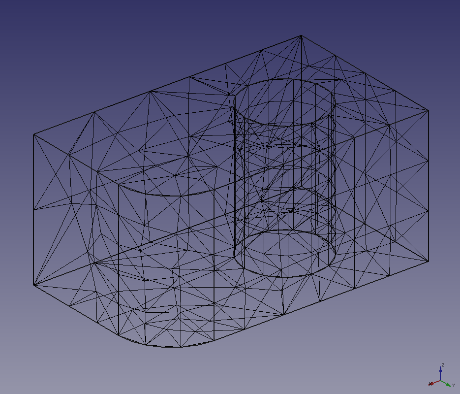
Enable quad dominant -
Gmsh
For gmsh mesher, you should specify the Gmsh executable to be used at first.
Set the [Path] of the dialog box to the executable file in the FreeCAD installation folder (for example, "C:¥Program Files¥FreeCAD 0.19¥bin¥gmsh.exe" by default on Windows) or the executable file downloaded from the Gmsh download site.
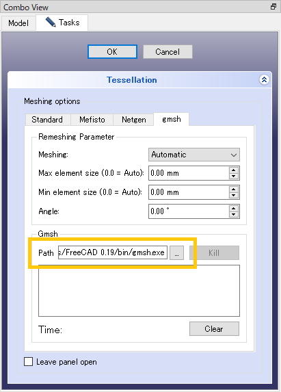
Gmsh path setting Parameter Behavior Meshing Meshing method (Adaptive, Delaunay, etc.). Max element size Maximum mesh size. The smaller the size, the finer the mesh. Automatically set to 0. Min element size Minimum mesh size. The smaller the size, the finer the mesh. Automatically set to 0. Angle The angle threshold used to divide surfaces. 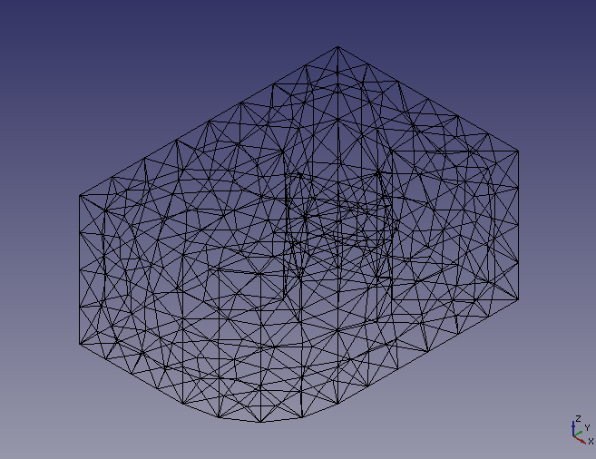
Meshing=Automatic
Max element size=0 (=Auto)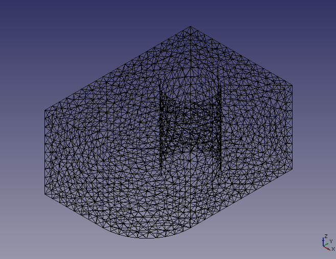
Meshing=Automatic
Max element size=5 mm
-
Set paramters in the dialog box and click OK to create mesh.
-
Select the meshed solid on model tree and type space key to hide it. Then select [View]-[Draw style]-[Wireframe] in menu bar to set 3D view wireframe display mode. Now you can see the generated mesh clearly.
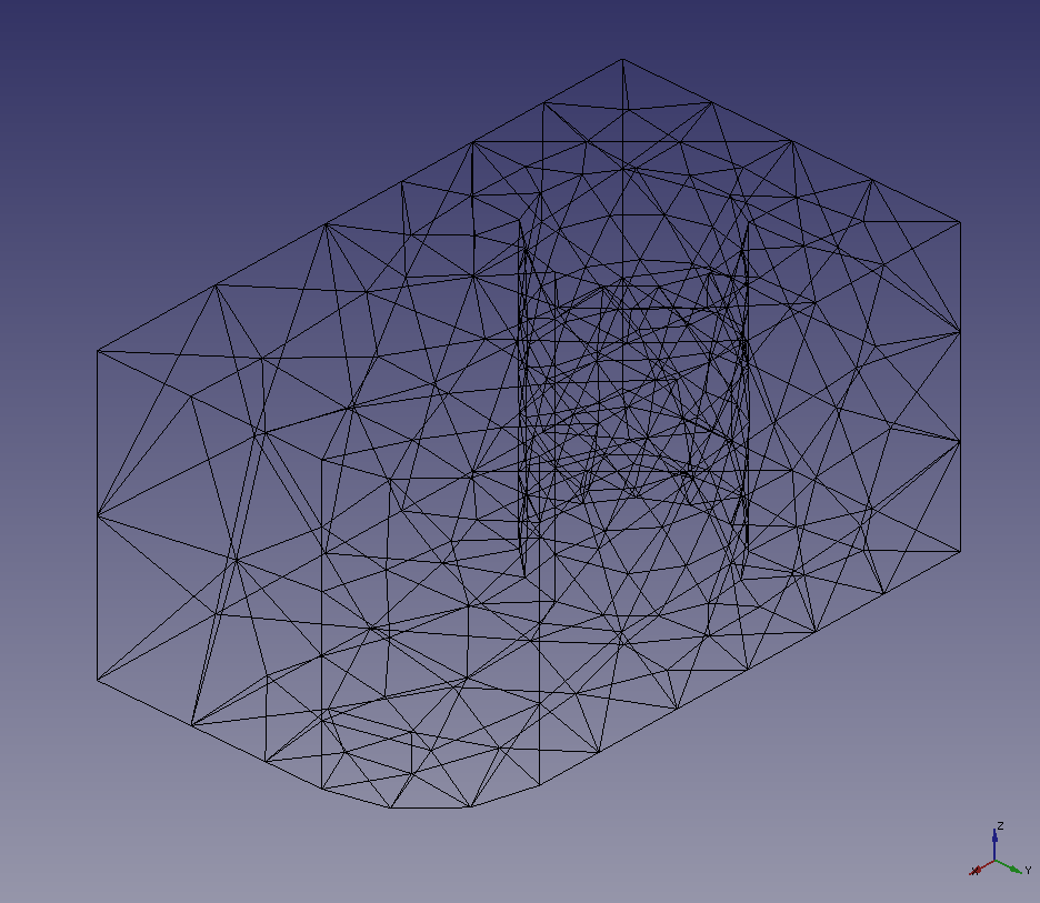
Wireframe display mode -
If the mesh has no problem, select it in the model tree and export it with "Export mesh"
 .
.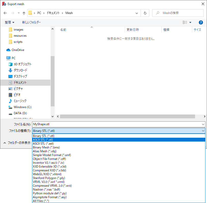
Dialog box for mesh exporting Following formats can be used for exporting.
- Binary STL (*.stl)
- ASCII STL (*.stl)
- ASCII STL (*.ast)
- Binary Mesh (*.bms)
- Alias Mesh (*.obj)
- Simple Model Format (*.smf)
- Object File Format (*.off)
- Inventor V2.1 ascii (*.iv)
- X3D Extensible 3D (*.x3d)
- Compressed X3D (*.x3dz)
- WebGL/X3D (*.xhtml)
- Stanford Polygon (*.ply)
- VRML V2.0 (*.wrl *.vrml)
- Compressed VRML V2.0 (*.wrz)
- Nastran (*.nas *.bdf)
- Python module file (*.py)
- Asymptote Format (*.asy)