FreeCAD: Tutorial TechDraw workbench (1/3)
Summary
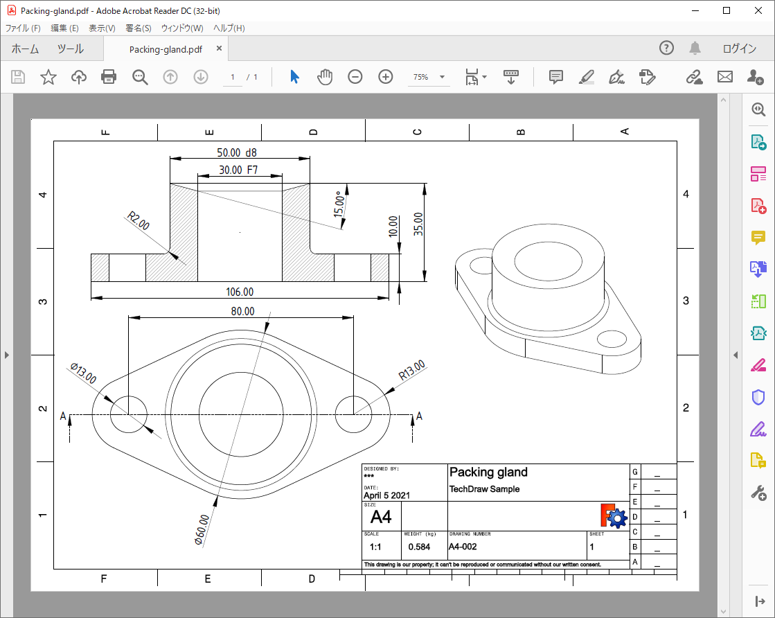
In this tutorial, we will create a 2D drawing from a 3D shape and output the drawing as PDF file (You can download the PDF file from "Drawing PDF file").
Creating new drawing page
-
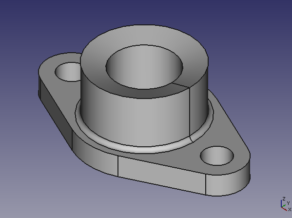
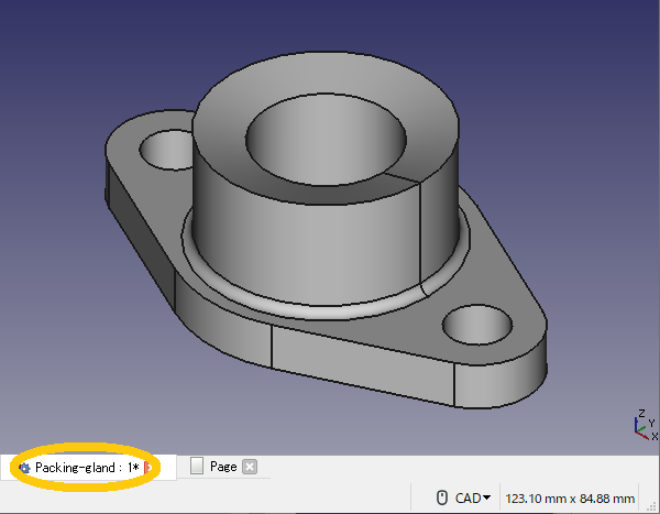
Run FreeCAD and create a 3D shape, or load a shape from a STEP file or other source (You can download the shpae that is used in this example from "FreeCAD file of a sample shape").
The shape to be made into 2D drawing Switch workbench to TecDraw workbench
 .
.-
Add new drawing page from template
 and select "A4_LandscapeTD.svg". By this operation, new A4 size landscape drawing page will be added.
The drawing page can be zoomed in/out with the mouse wheel and paned with left-click dragging.
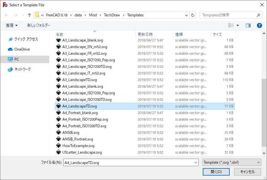
Dialog for template selecting 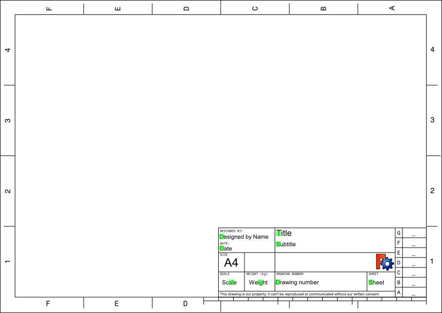
New page
Adding views to drawing page
We will add shapes to the drawing page. The shape will be drawn in the page at the viewpoint position of the 3D view when it is added.
-
Select a tab at bottom of the window to show 3D view and change viewpoint to axonometric view
 .
.
Tab at bottom of the window -
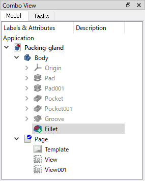
Slect the shape (for example the "Fillet") to be added to the drawing in model tree and add it to the page
 . The added view can be moved in the page by dragging the border around it. If you want to delete the view, select it with mouse and push Delete key.
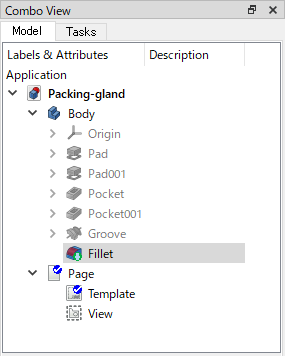
Model tree when adding a view 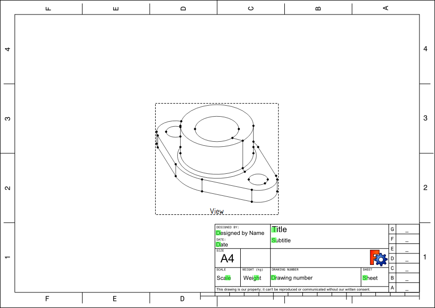
Adding viwe to the page -
Return to the 3D View screen again, change viewpoint to the top view
 .
.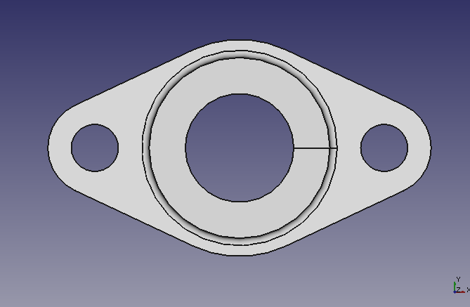
Changing viewpoint to the top view in 3D view -
In similar way of the first view, select the shape you want to add to the drawing in the model tree and add the view to the page
.Adjust the position of each view on the drawing page by dragging the border that appears around the view.
Model tree when adding the second view 
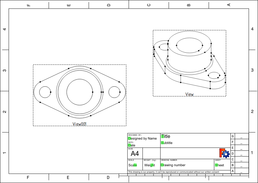
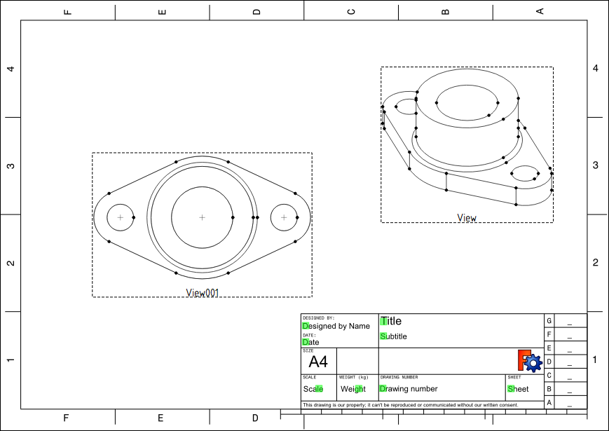
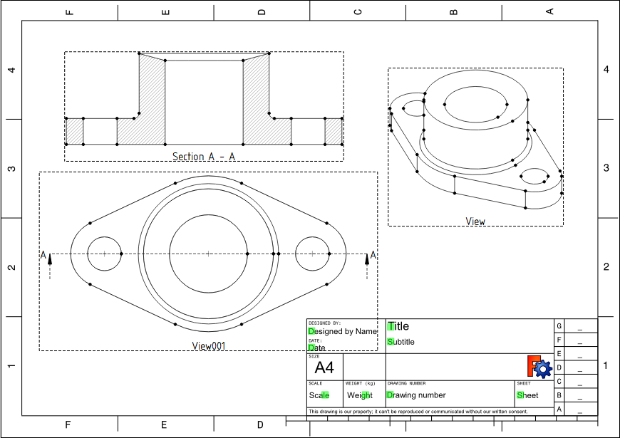
Page with two views
Adjusting the drawing
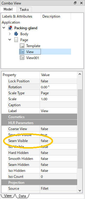
Hide seam lines
In default, the seam lines has been visible as in 3D view. So we will set them to be hidden. Click the adding view on drawing page to select and set "Seam Visible" property to "false" at Data tab of Combo view. When you push F5 key on keyboard to refresh the entire page, the seam lines will be hidden. Hide seam lines in both views.
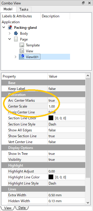
Showing center mark of a circle
Show the center marks of the circles and arcs, because we will need them later when we add dimensions. On the drawing page, click top view (View001) to select, and on the View tab of the Combo view, set "Arc Center Marks" property to "true" and "Center Scale" property to "1". Press the F5 key on keyboard to refresh the entire page and show the center marks of the circle.
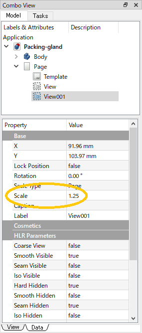
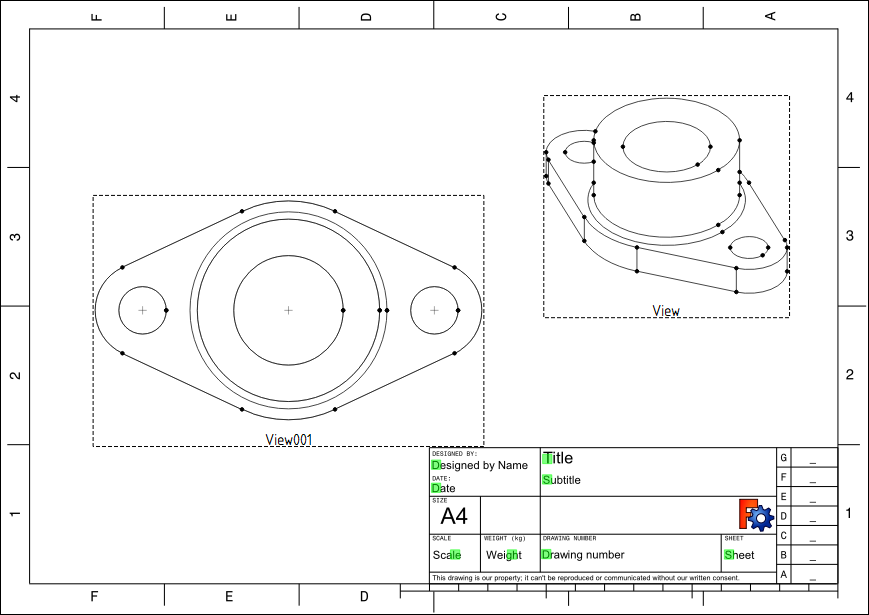
Scaling the views
On the drawing page, click top view (View001) to select, and on the View tab of the Combo view, set "Scale" property to "1.25". Press the F5 key on keyboard to refresh the entire page. The top view will be enlarged 1.25 times.
If you want to rotate the view on the page, enter rotational angle to "Rotation" on Data tab.
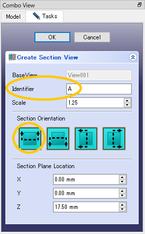
Adding cross-section view
On the drawing page, click top view (View001) to select, and add cross-section . Click the leftmost button in the center of the dialog, enter "A" in the "Identifer" field, and click to create the cross-section.
Now we have the basic elements in the drawing. The next step is to add dimensions to the drawing.