FreeCAD: Tutorial TechDraw workbench (2/3)
Adding dimensions
Length dimension
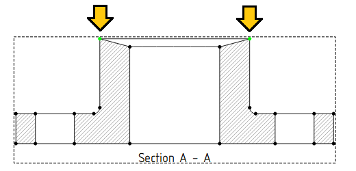
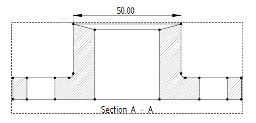
Select two points (or one line) on the page with holding down the Ctrl key and execute the Horizontal Distance Dimension to add a horizontal length dimension. You can adjust the display position of the dimension by dragging the number of the dimension with the mouse (if you want to delete the added dimension, select it with the mouse and press the Delete key).
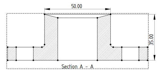
In similar way, select two points (or one line) on the page with holding down the Ctrl key and execute the Vertical Distance Dimension to add a vertical length dimension.
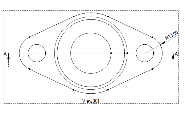
Arc radius dimension
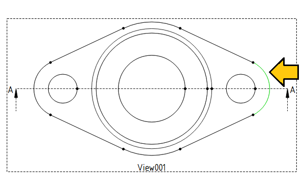
To add an arc radius, select the arc on the page and execute Radius Dimension .
.
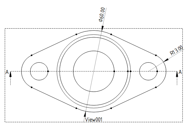
In similar way, you can add a diameter dimension by selecting an arc and executing Diameter Dimension .
.
Angles
Select 2 lines that make an angle on the page and run Angle Dimension to add an angle dimension.
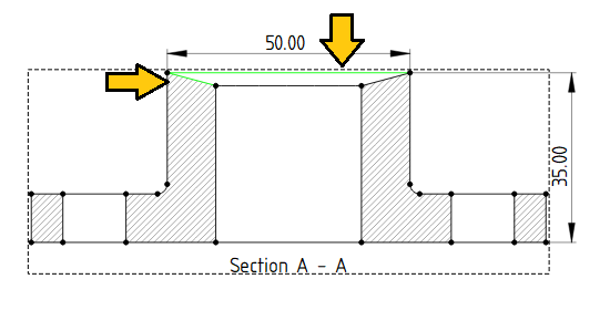
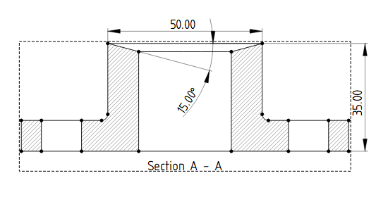
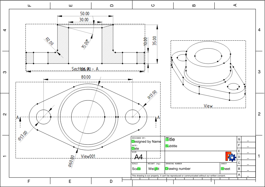
When all the dimensions is added, it will look like following.
Adjusting dimensions
Adding symbols and character string to the dimensions
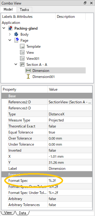
You can adjust the formatting by selecting the dimension on the page and changing the "Format Spec" property in the Data tab of the Combo View. The default is "%.2f", but you can add any string you like, for example, "%.2f mm". Press F5 key on keyboard to refresh the entire page and reflect the changes.
You can also set "Arbitrary" property to "true" to display the input string of "Format Spec" as it is on the drawing (regardless of the actual dimensions).
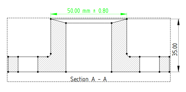
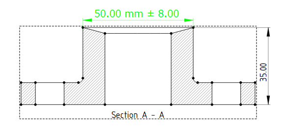
Dimensional tolerance
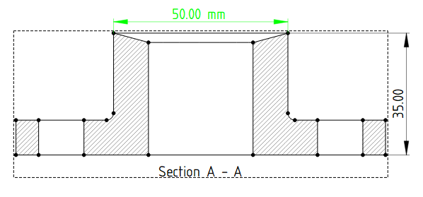
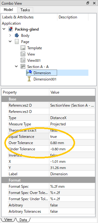
You can add an upper and lower tolerance to the dimension by selecting the dimension on the page and changing the "Over Tolerance" property in the Data tab of the Combo View. If you want to set different values for the upper and lower limits, set "Equal Tolerance" property to "false" and set the lower tolerance in "Under Tolerance" property. Press F5 key on keyboard to refresh the entire page and reflect the changes.
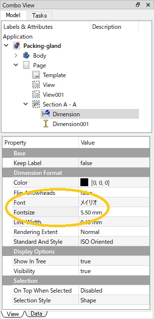
Font
Select the dimensions on the page and change the font type and size by changing "Font" property and "Fontsize" property in the View tab of the Combo View. pressing F5 will refresh the whole page to reflect the change. Press F5 key on keyboard to refresh the entire page and reflect the changes.
Using the "Adding symbols and character string to the dimensions" function above, adjust the formatting in the 2 places on the page shown below (d8 and F7 represent fit tolerances).
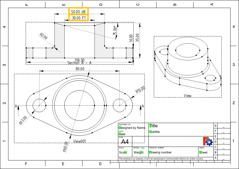
Finally, we will edit the description for the drawing and output the drawing as a PDF file.